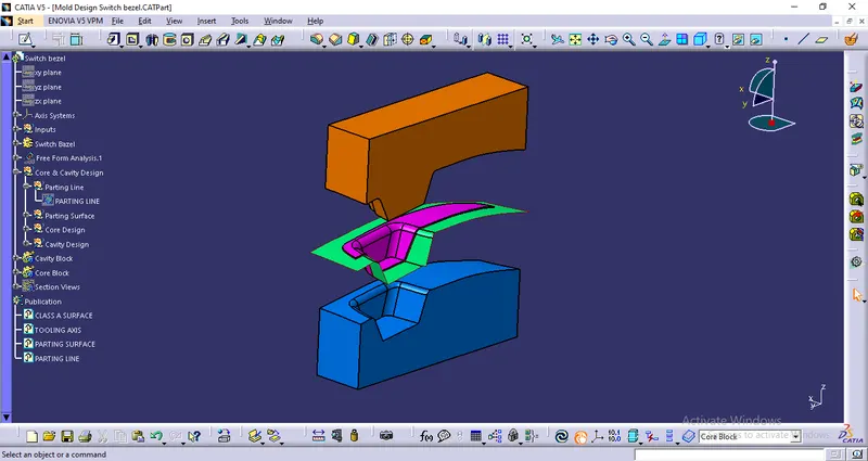
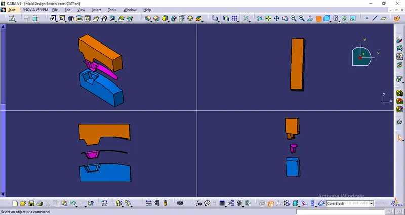
Week 8 - Challenge 5 - Core & Cavity Design
Core & Cavity Design
Create the core and cavity blocks for the switch bezel.
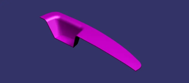
Understanding Core and Cavity of plastic component
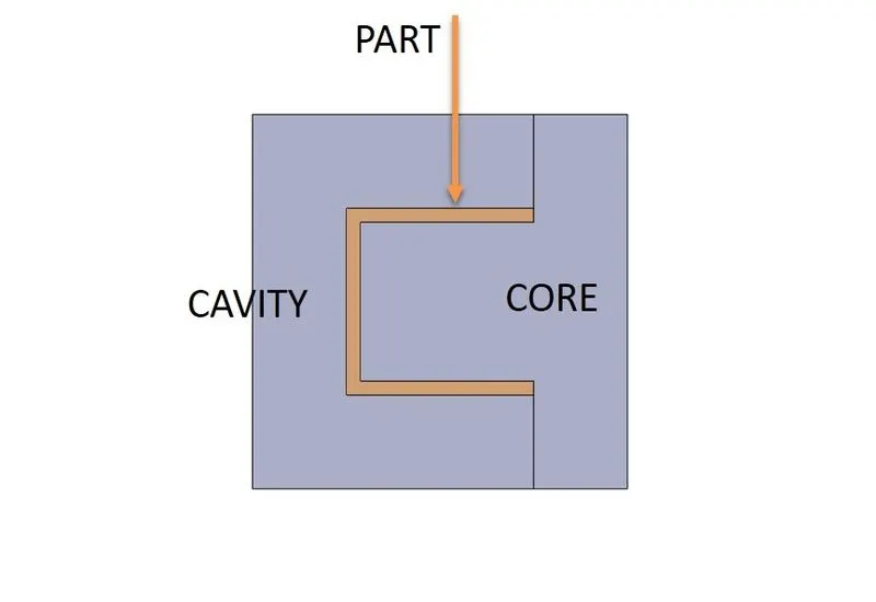
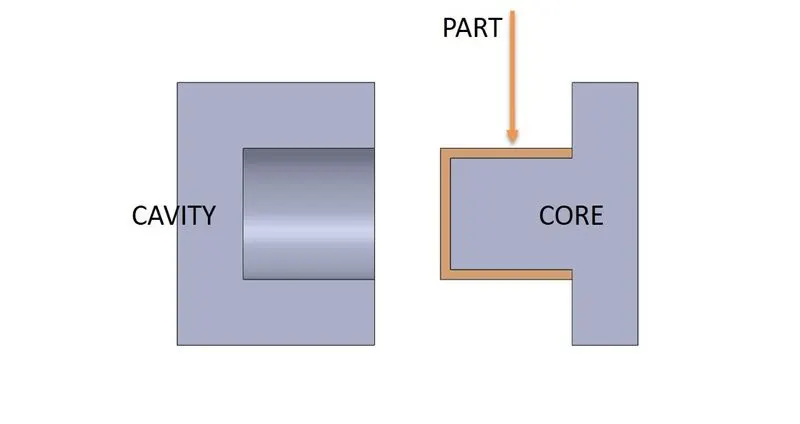
The injection molding process uses molds, typically made of steel or aluminum, as the custom tooling. The mold has many components, but can be split into two halves. Each half is attached inside the injection molding machine and the rear half is allowed to slide so that the mold can be opened and closed along the mold’s parting line. The two main components of the mold are the mold core and the mold cavity. When the mold is closed, the space between the mold core and the mold cavity forms the part cavity, that will be filled with molten plastic to create the desired part. Multiple-cavity molds are sometimes used, in which the two mold halves form several identical part cavities.
Parting Surface
Designed for the removal of the plastic product and the cold slug, the parting surface is where the core meets the cavity, and usually locates at the largest section of a product.
The concept of a parting line is similar. It is a line that splits the mold into two parts – the core and the cavity. The intersection line of Class B and C surface.
When designing a plastic injection mold, the selection of the parting surface is an important design factor. With a reasonable parting surface selection, the mold structure can be simpler, making it easier to mold and release the plastic product, with product quality guaranteed. If the parting surface is inappropriately selected, mold structure becomes complex, making it difficult to mold the plastic product, thus affecting product quality. Therefore, the selection of the parting surface is of great importance to the design of mold structure.
Forms of Parting Surface

- Flat Parting Surface
- Angled Parting Surface
- Stepped Parting Surface
- Curved Parting Surface
Create the Core and cavity blocks for the switch bezel using CATIA V5
Draft Analysis
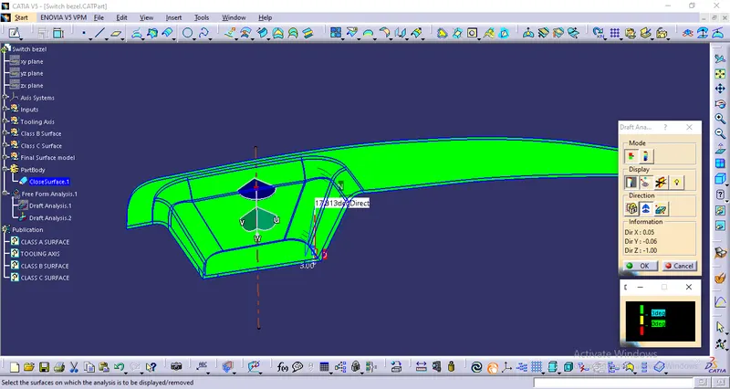
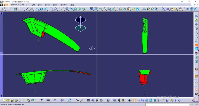
- In these models where C surface is in parallel to tooling direction, A and C surface should be in same colour during draft analysis regardless of the pulling direction
As the model lies in green zone in the draft analysis which suggests that all faces have minimum 3 degree draft angle, which further makes the part manufacturable.
1. Creating Parting surface
Create boundary in the A surface-
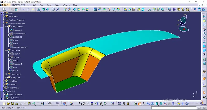
Using the boundary extrapolate-
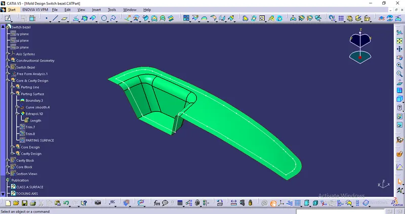
Using Class A, B & C surfaces create a parting surface on B surface side-
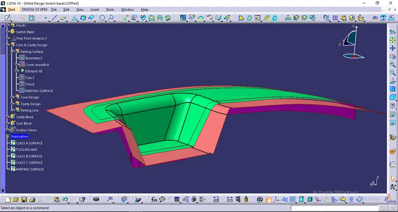
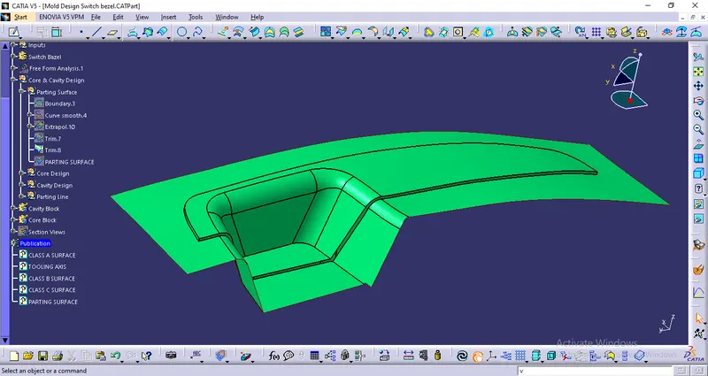
Final Parting surface-
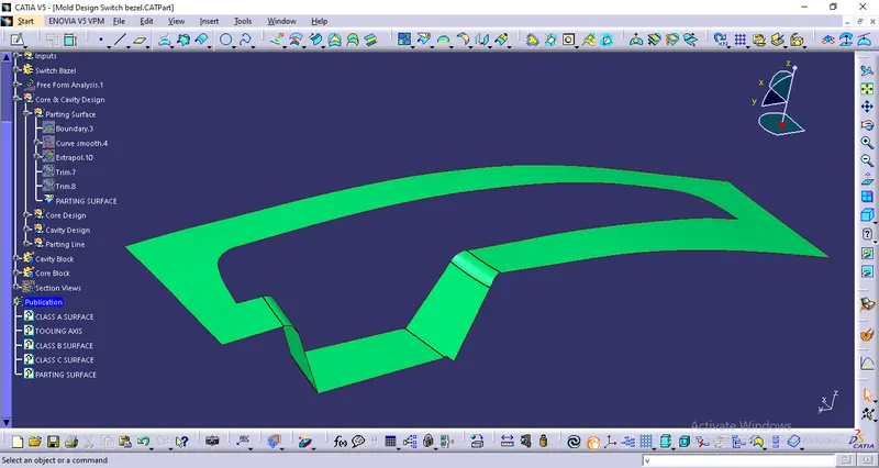
Parting Line-
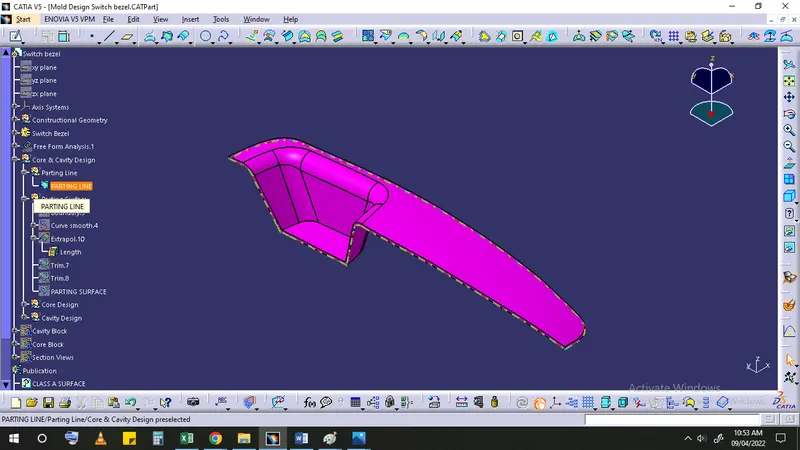
2. Creating Core and Cavity
Create sketch for the outer mold surface
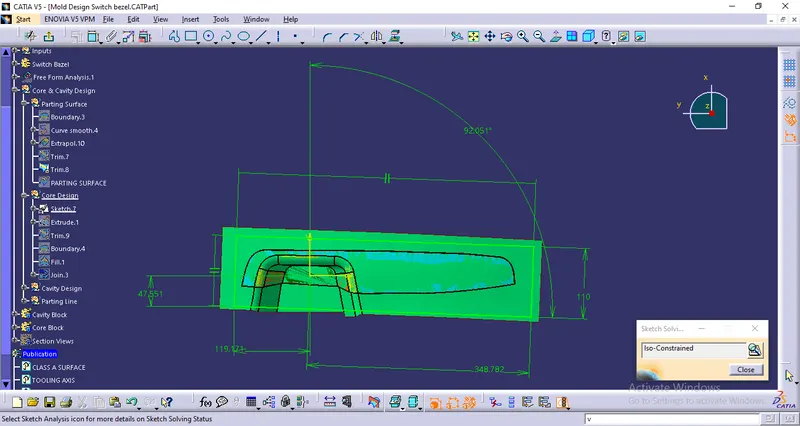
Extrude the surface for mold-
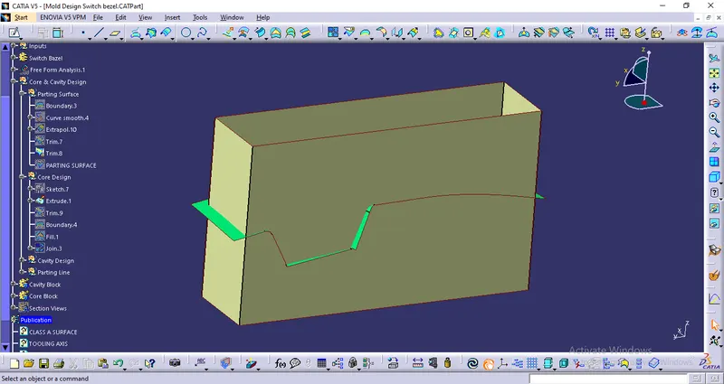
Using parting surface trim off the mold surface to get core-
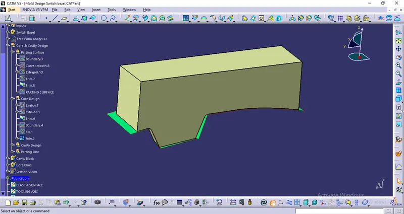
Using B surface trim off mold surface to get cavity-
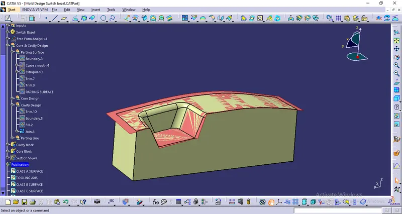
Close top end and create solid core and cavity block using close surface-
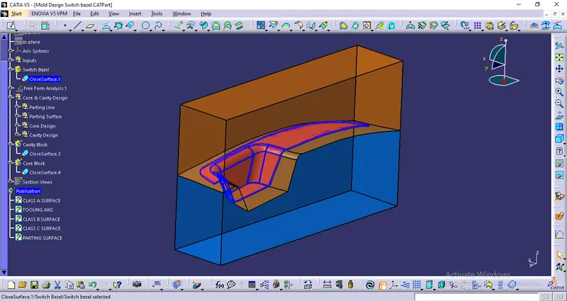
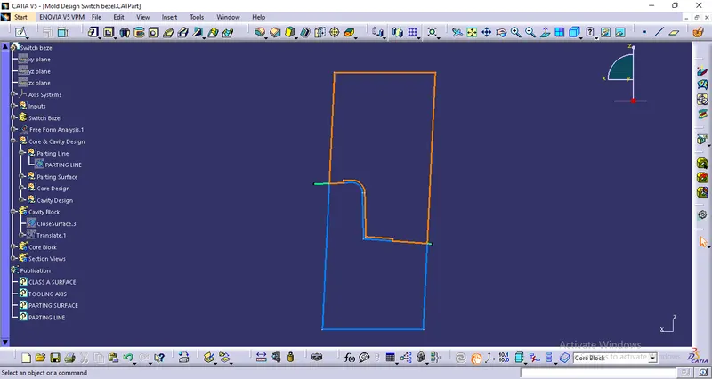
Core and Cavity-