Week 8 - Challenge 5 - Core & Cavity Design
AIM
To create a door arm rest switch bezel from the given Class A surface by adding a thickness of 2.5 mm to it and to create the core and cavity blocks for the switch bezel.
PROCEDURE:
1)Tooling axis
Tooling axis is nothing but the direction in which the core and cavity open and closes . Design engineer works is to analyse the class A surface and find out the best possible tooling direction keeping in mind all the draft angle is with respect to the tooling axis so that the component can be easily ejected from the moulds.
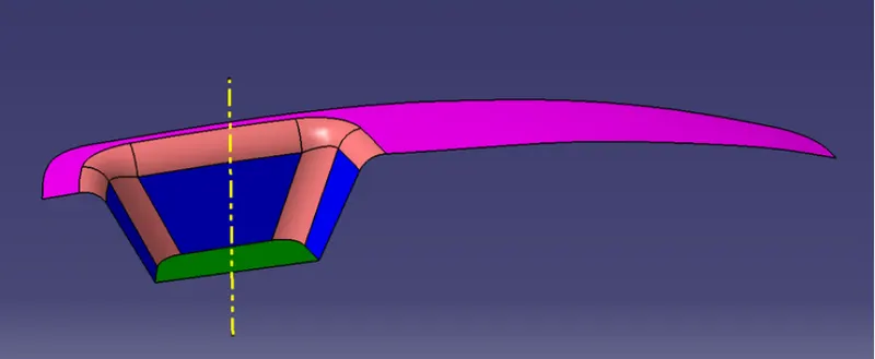
2) Class A surface
In automative design, a class A surface is any of a set of freedom surfcaes of high efficiency and quality .Although, strictly,it is nothing more than saying the surface have curvature alignment-to ideal aesthetical reflection quality, many people interpret class A surface to have G2 (or even G3) curvature continuity to one another. Class A surfacing is done using computer aided industrial design application. Class A surface modelers are also called " digital sculptors" in the industry.Industrial designers develop their design styling through the A surface ,the physical surface the end user can feel,touch,see etc.
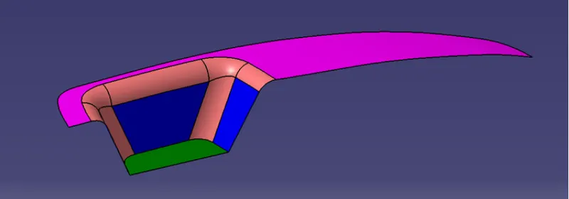
3)B Class surface creation
Represent internal and functional surfaces. This xluster exemplary includes derived surfaces created by offset operation from class A surfaces to define the thickness of material .In this file it is important to link class B surfaces geometrically to enable an adoption to class A surface automattically in case of styling change.
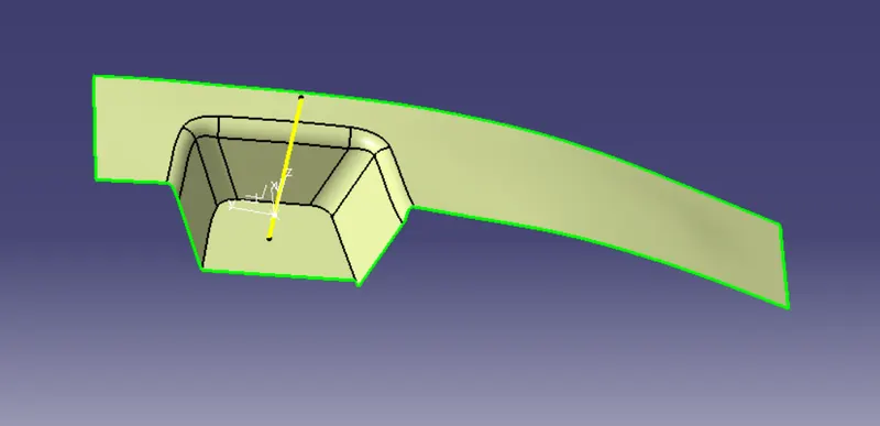
After creating the tooling axis .Bsurface is to created which is nothing but the surface parallel to the A surface .B surface contains all the fillets and the edge which the A surface contains.
4) C Class Surface Creation
Class C surface is swept along the boundary of the class A at an angle perpendicular to the Class A surface with respect to the tooling axis direction with a draft angle of 3 degree.
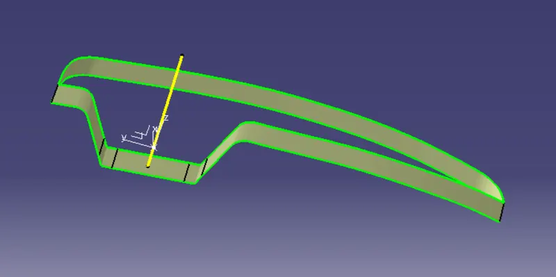
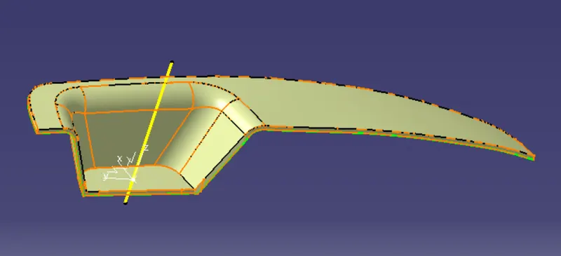
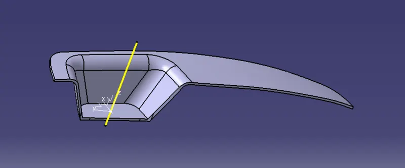
5)Joining Class A,B AND C surface to get a closed surfaces
After finishing all the 3 surfaces , join the class A and class C surface togther using the join command .Now the joined surfaces are the trimmed with class B surface to form a closed surface.
6)Draft Analysis
The Draft analysis command enables you to detect if the part you drafted will be easily removed .This type of analysis is perdformed based on colour ranges identifying zones on the analysed element where the deviation from the draft direction at any point, corresponds to specified values.
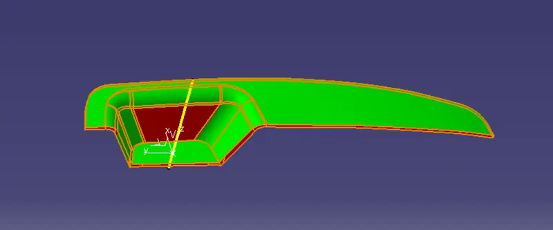
Draft angles are very important in thermoforming product design. If the product is formed onto a female or negative mold. It shinks away from the mold sidewalls .As a result ,true female or negative products can be thermoformed with vertical walls having zero draft angles.
7) Core and cavity design
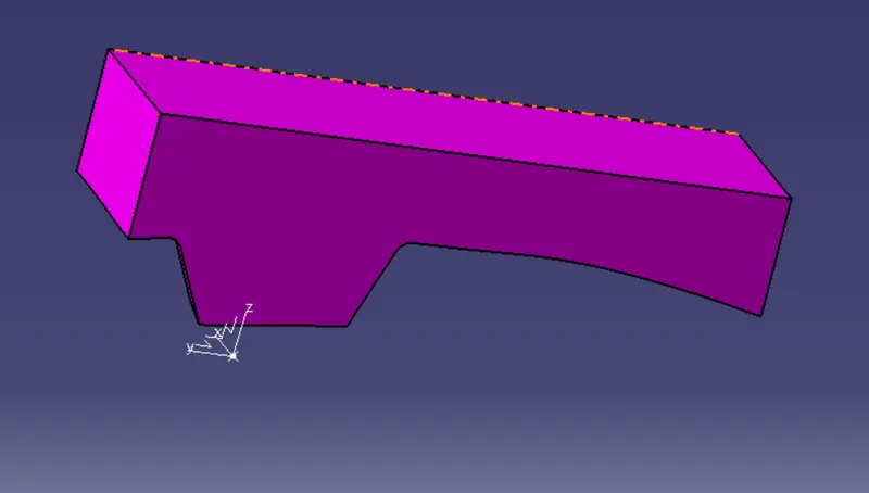
The mould core & cavity are the shaped sections in either half of the mould tool which give the plastic product its final shope.The hot molten material is injected into the core & cavity and then sets hard into shape. The design of the core & cavity is essential in the correct formation of the product .The sequence of events during the injection mould of a plastic is clalled injection moulding cycle.The cyle begins whwn the mold closes, followed by the injection of the polymer into the mold cavity.A core is usually made of the best quality sand and is placed into desired positon in the mould cavity .Core prints are added to both sides of the pattern to create impressions that allow the core to be supported and held at both ends.
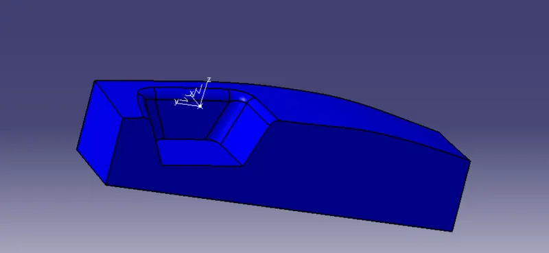
8)Parting Line and Parting Surface :
A parting line , in industrial casting of molds , is the border line in which draft angles change direction .That is, it is the dividing line that splits the core and cavity halves of a moulded part.It is sometimes a starting point for the mould parting surface.In engineering drawing parting line is often abbreviated as PL ASME's Y12.8 standard specifies a symbol for parting line.Engineering application( seals, tight running moulded parts) that require precision for shape control,call for removal of flashes .Many molders will repair or even replace the mould tooling so that the flash is reduced ta an acceptable tolerance or eliminated altogether.Secondary operations to remove parting line flash include hand triming. Vibratory tumbling media blasting and cryogenic deflashing.
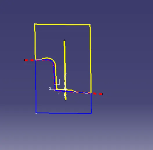
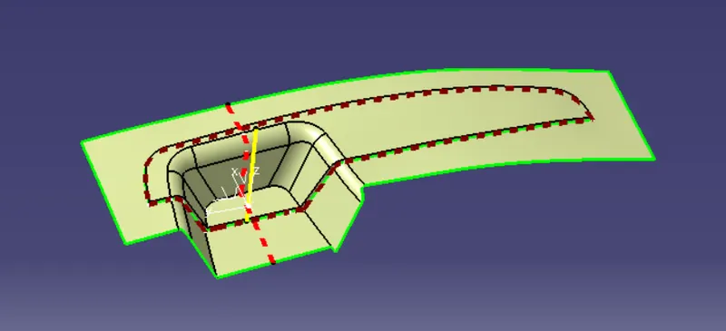
The parting surafce of amould are those surfaces of bith moulded adjacent to the impression which butt together to form aseal and prevent the loss of plastic material from the impression .The parting surfaces of a mould are those portion of both mould plates ,adjacent to the impression ,which butt together to form a seal and prevent the loss of plastic material from the impression.
Result:
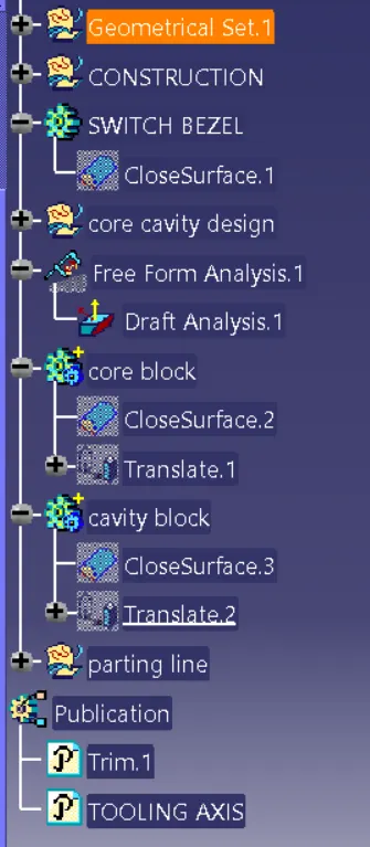
Class A,B and C surface was created as per the automotive standards using catia v5
core and cavity for the above model was created.