Week 8 - Challenge 5 - Core & Cavity Design
Aim :- To create Core & Cavity for th given switch bezel component, highlighting the Core and Cavity including the parting surface and parting lines.
Procedure :-
- The given model has a class-A surface. since the class-B and C surfaces are already created and the draft analysis is done on the component. insert a geometrical set and rename it as core and cavity design. now extrapolate the class-A enough using point-continuity and unhide the class-C trim surface.
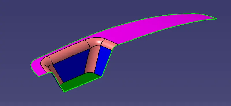
- Trim the two surfaces together to get the half portion of the core part. a parting surface is created which differentiates the core & cavity portions.
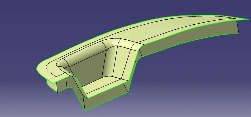
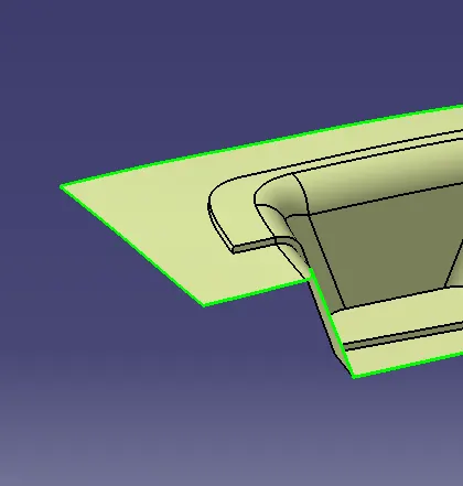
- Create a positioned sketch across the surface from to view by inserting a axis system as reference and extrude the sketch enough using the tooling as direction. make sure the sketches are constrained.
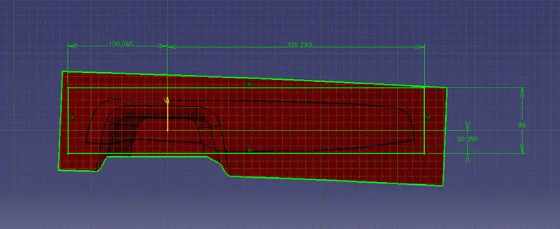
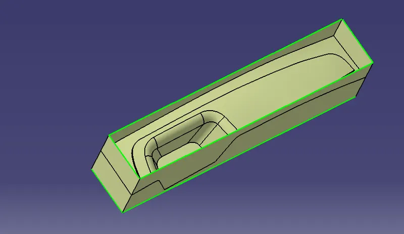
- Now trim the surfaces by removing the lower side walls of the surfaces. now close the upper surface using fill surface option and join/ trim them together to remove the boundry
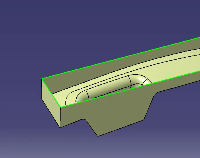
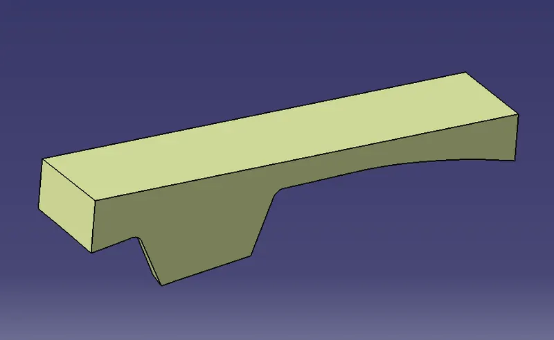
- Compare it with the class-A surface and visually inspect the surfaces. now go to part design and create the solid body out of the created closed surfaces.
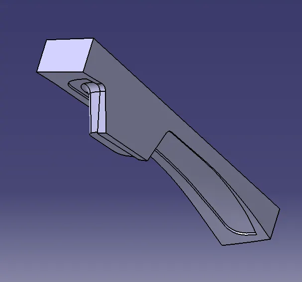
- Similarly insert another geometrical set for the cavity section. unhide the class-B surface and extruded sketch. trim them together to remove the upper side walls. now fill the open surface using filler surfaces from part design and make a solid out of it.
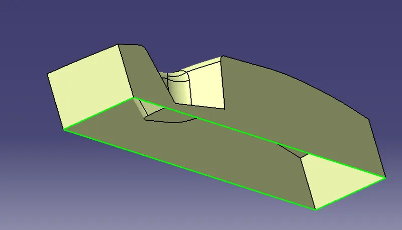
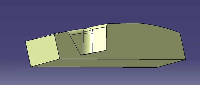
- Now goto part design and using close surface option create a solid body out of it. define the solid surfaces in th epart body. insert separate part bodies for core and cavity.
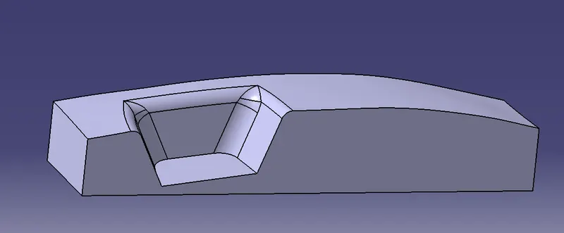
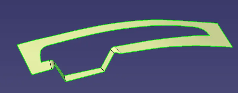
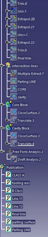
- Using the axis system intersect the XY-plane with the core , cavity , and parting surface. to create intersection lines which show clear representation of the surfaces. use multiple extract option from the class-B to extract the parting line.
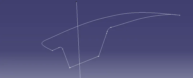
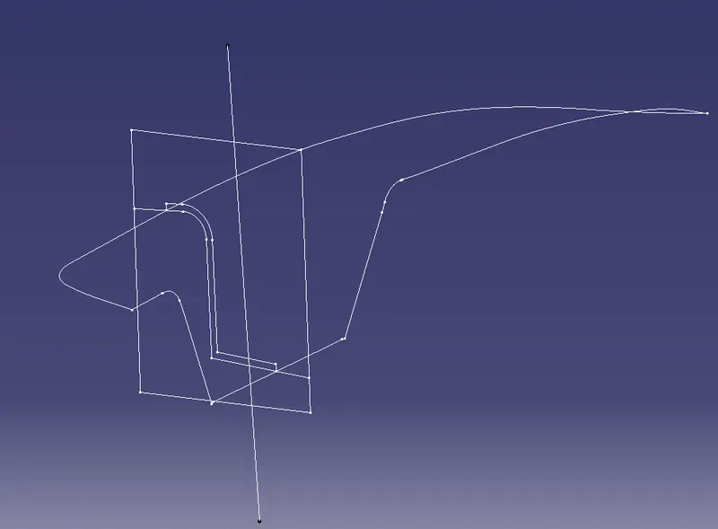
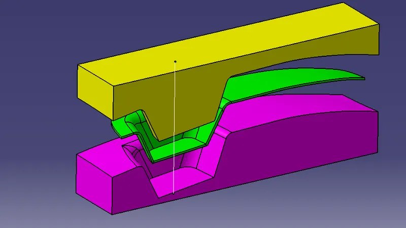
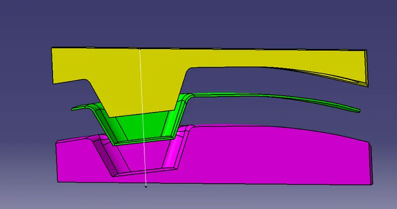
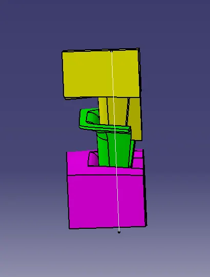
- Now unhide the part bodies together and translate the core and cavity solid sections to an approperiate distance away from the centre in the direction of tooling axis. add different colours to visually separate them also unhide the main part body.
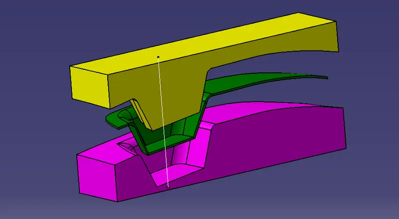
- Unhide the parting surface to get the actual view of the entire core and cavity design. use multi sections option to view the insude part of the solid bodies created. publish the parting surface and parting lines to locate them easily in the tree structure.
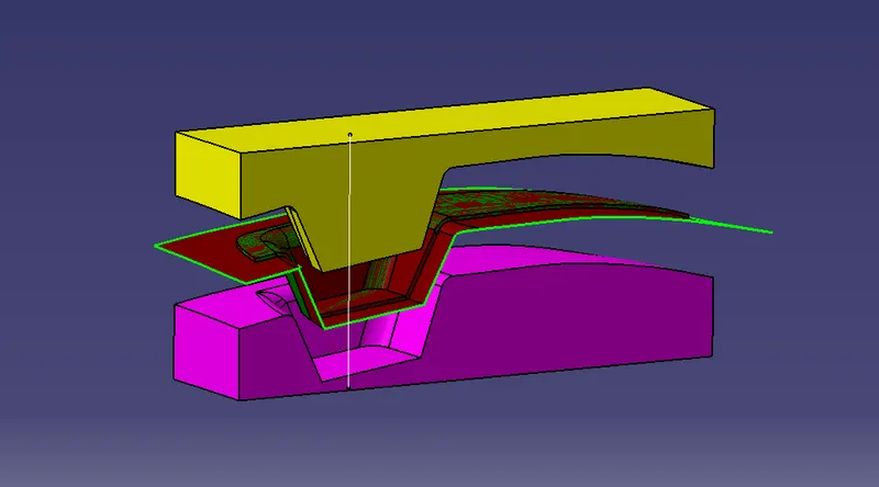
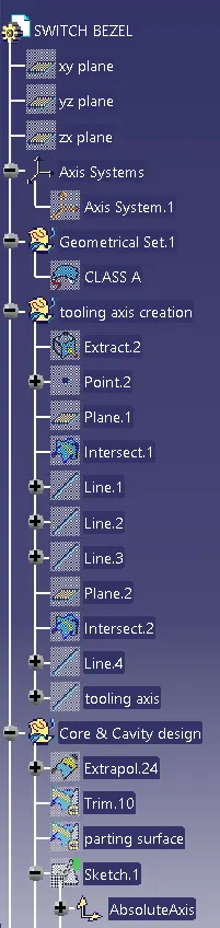
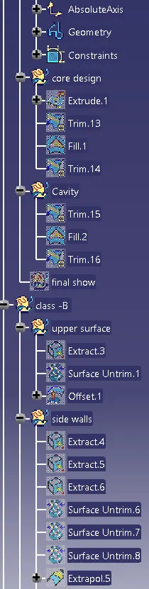
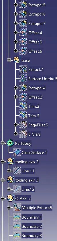
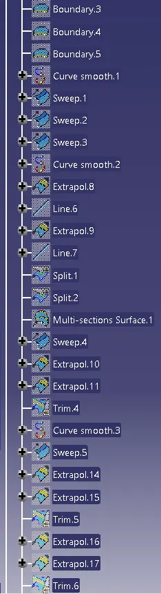
Model Tree :-
Result :-
Isometric view -
Front view -
side view -
MODEL DRIVE LINK :-