Week 8 - Challenge 4 - Coin Holder Design
COIN HOLDER DESIGN
Objective: To design Coin Holder Plastic Component through the given Class-A Surface and perform draft analysis on both the Class A Surface and the final model along the tooling axis meeting the requirements of the draft angle.
Introduction:
Class A Surface:
In automotive design, a class A surface is any of a set of freeform surfaces of high efficiency and quality. Although, strictly, it is nothing more than saying the surfaces have curvature and tangency alignment to ideal aesthetical reflection quality, many people interpret class A surfaces to have G2 (or even G3) curvature continuity to one another.
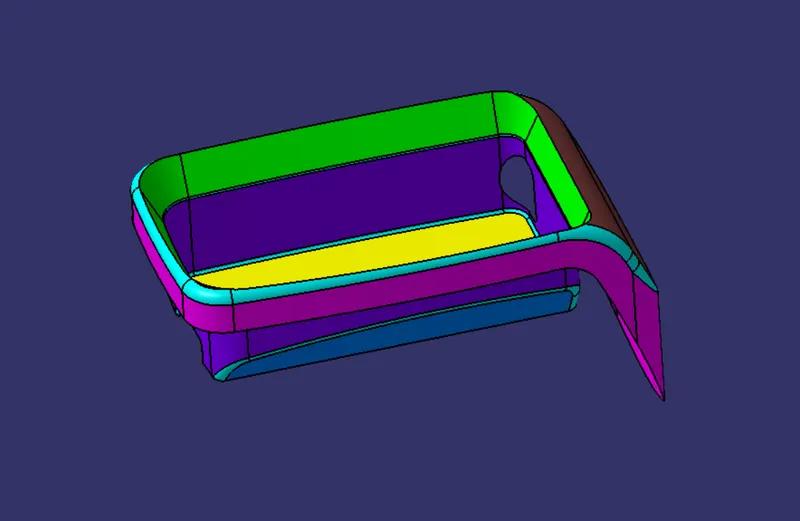
Class A surfacing is done using computer-aided industrial design applications. Class A surface modellers are also called ‘digital sculptures’ in the industry. Industrial designers develop their design styling through the A surface, the physical surface the end user can feel, touch, see etc.
Class B Surface:
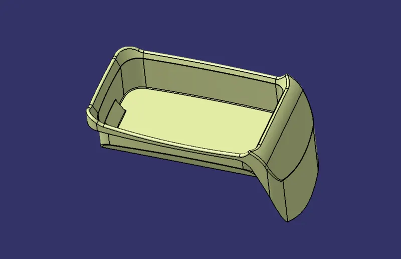
Class B Surface is a surface below a certain thickness from a Class A Surface. We can also say that it is an engineering surface because it contains all the engineering aspects of the model which is required.
Class C Surface:
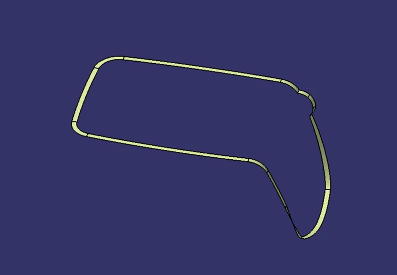
Class C Surface is a surface that joins the Class A Surface with Class B Surface.
Tooling Axis:
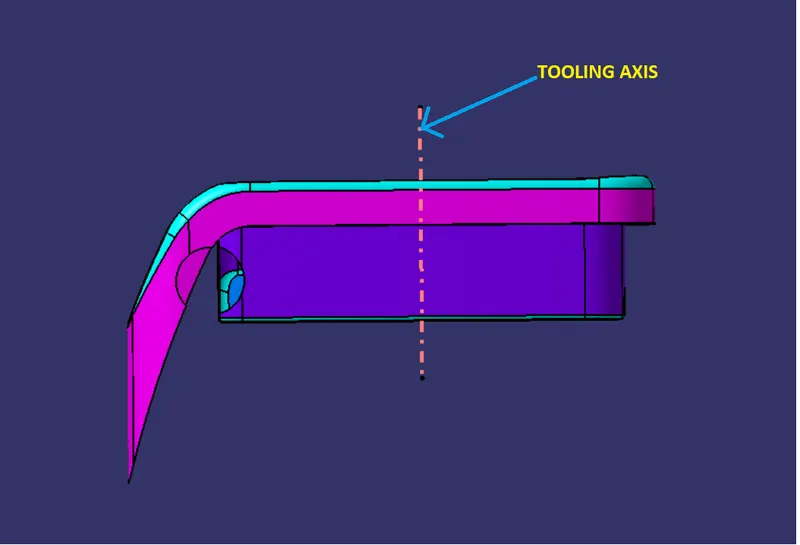
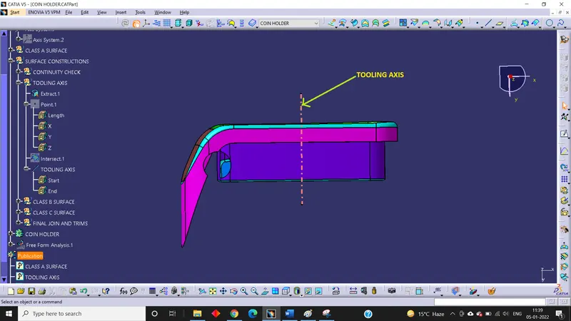
Tooling axis is the direction in which the mold or core and cavity opens.
Draft:
Draft is the angle in which the part is tapered to allow it to release. As the part cools, it tends to shrink to the core side of the mold. Draft is required on all parts in the direction of mold movement in order to allow parts to release or eject from the mold properly.
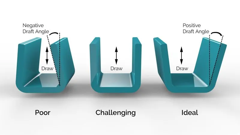
Most parts or applications require a minimum of 0.5 to 1 degree, however 3 degree is widely accepted as normal.
Draft Analysis:
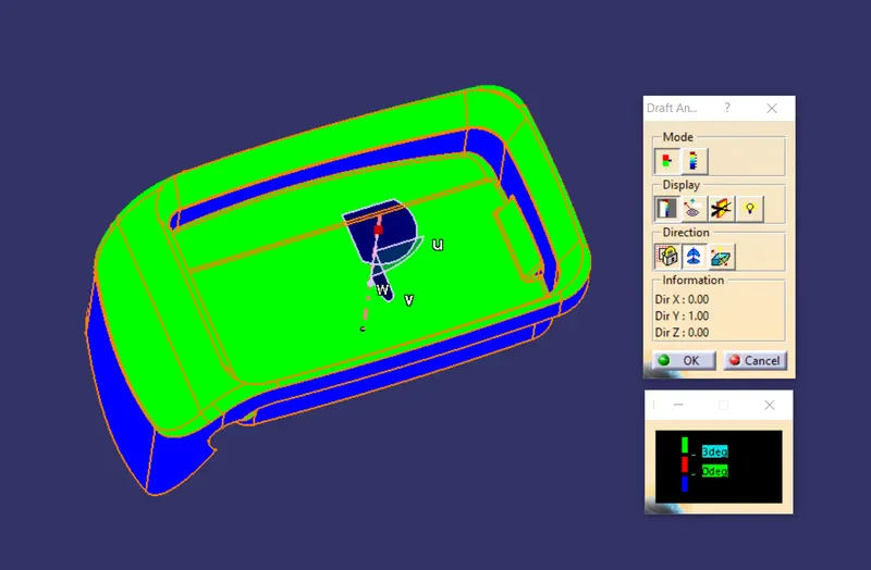
Draft analysis is done in order to detect if the part that has been drafted will be easily removed or not. This type of analysis is performed based on the colour ranges identifying zones on the analyzed elements where the deviation from the draft direction at any point corresponds to the specified values. When the draft analysis passes, it means our part is easily toolable or can be easily ejected.
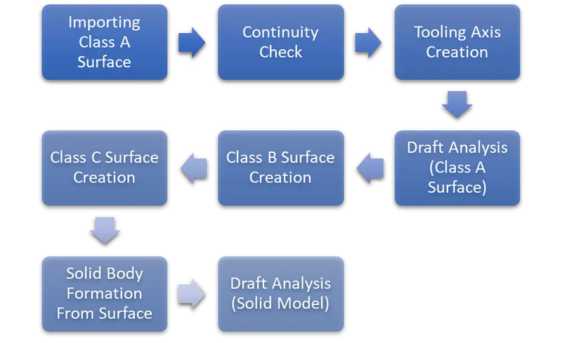
Methodology/Approach:
Procedure:
1. Importing Class A Surface:
First of all, we have to import the class A Surface into the Catia V5 Software.
2. Continuity Check:
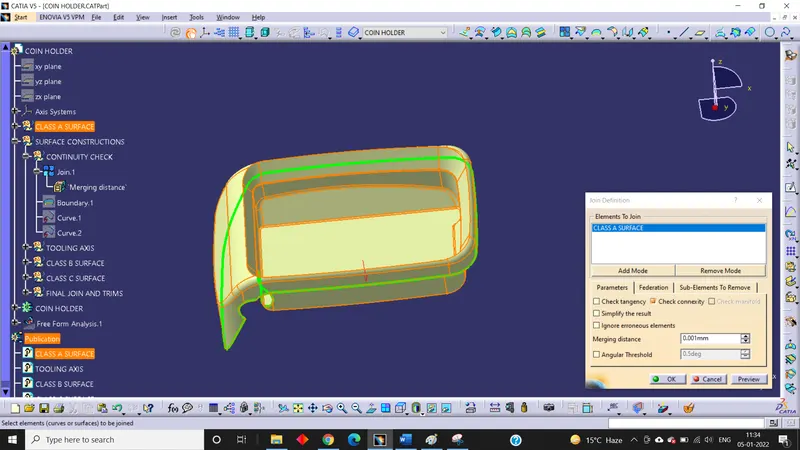
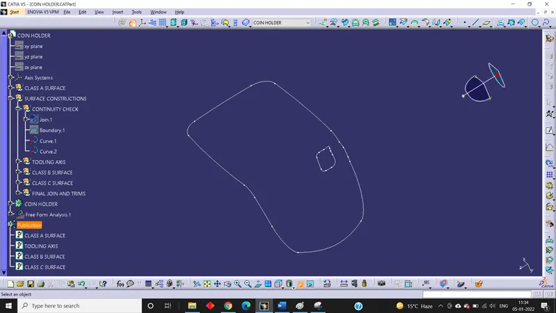
After getting the Class A Surface from the styling team, we have to ensure that the Class a Surface is properly joined and has no discontinuity on it. To check that we have to use the Boundary command or Join command.
3. Creation of Tooling Axis:
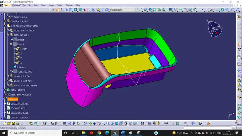
First of all, we have to analyse manually or visually to see which direction is the most appropriate for tooling axis. After analysing we found that Z-direction seems easy to be tooled. So, we use the bisecting line method to create the tooling axis. For that we extract the base and create a point on the surface at 00 mm. After that we create an axis system on the same point and intersect the YZ plane with Class A Surface. Here we found that the walls are at 0 degree to the normal which will be very difficult to manufacture as the plastic part would not eject at the end due to contraction after the cooling process is completed.
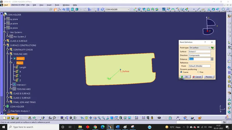
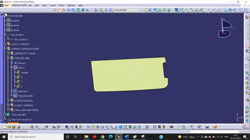
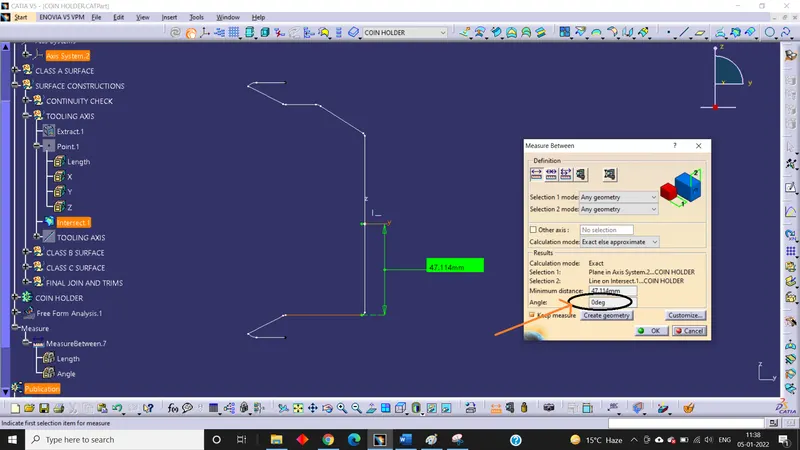
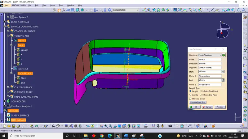
So, we have to contact with the styling team to give a minimum draft to the surface. But here, we will proceed with the same Class A Surface. So, for that we create a line on a point that was created earlier using point and direction option giving the extract as a direction which means the line is normal to the surface. This is our main tooling axis.
4. Draft Analysis of Class A Surface:
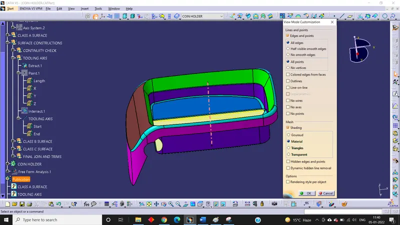
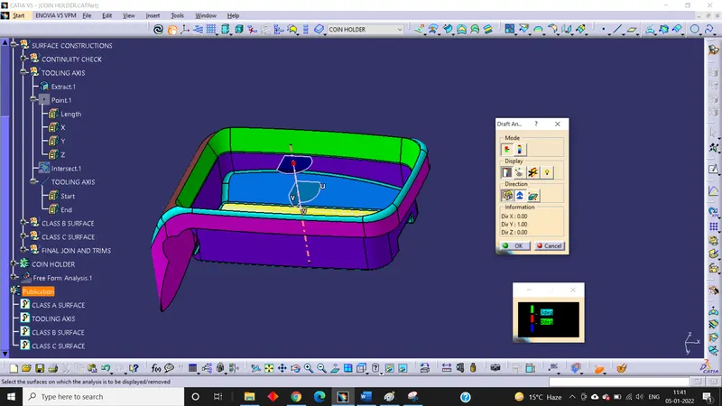
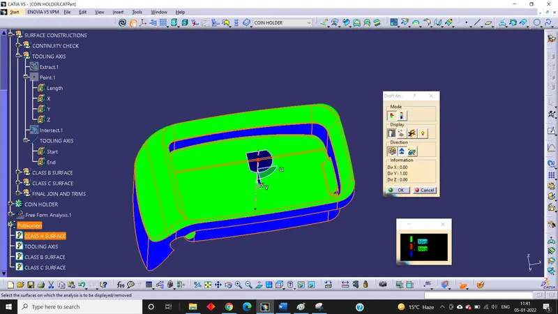
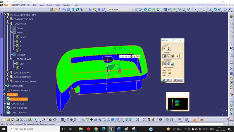
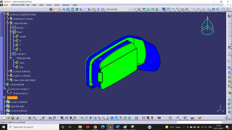
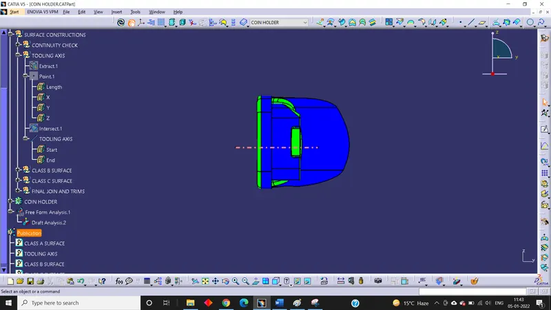
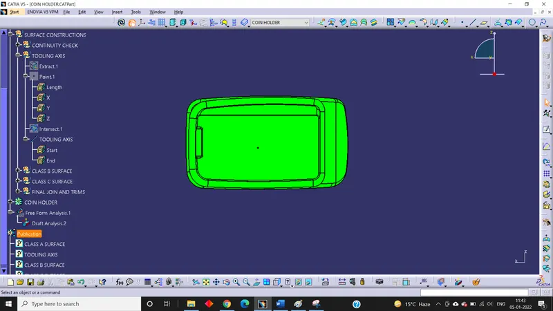
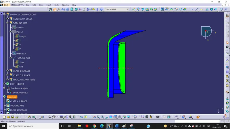
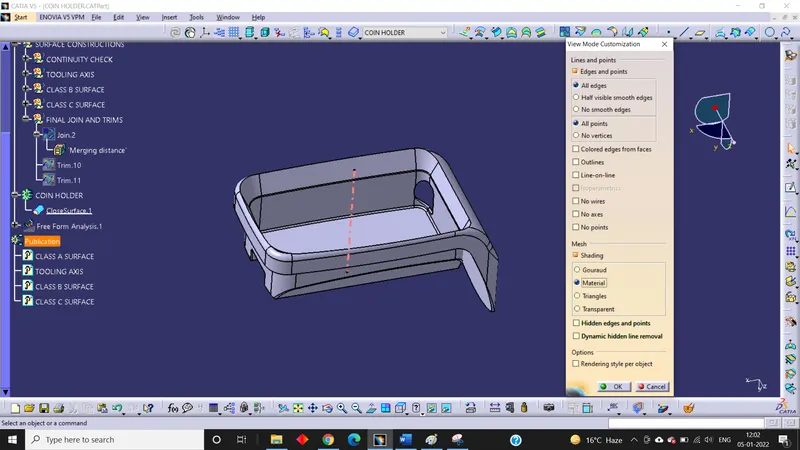
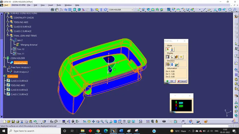
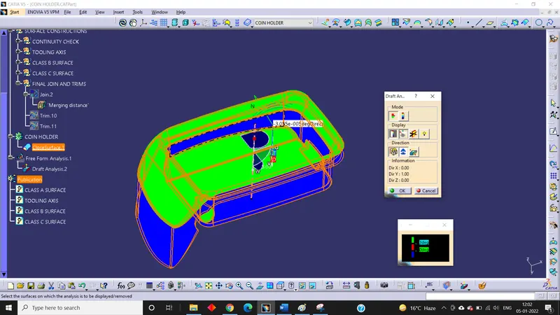
First of all, we should change the view to the Customize View parameters and then select the material mode and then Ok. After that we will open draft analysis command and then click on the compass icon and then align the compass of the window with the tooling axis earlier created and then lock the draft direction. After that click on the surface and see that the surface is within permissible limit of the draft value. The surface should be green and in the column 3 degree should be inserted. But we found that the side wall and the outer flange are not clearing the draft in z direction as they are turned into blue. This is because the Class A Surface has not the minimum angles on the side walls and the outer flange.
Isometric View:
Front View:
Side View:
Top View:
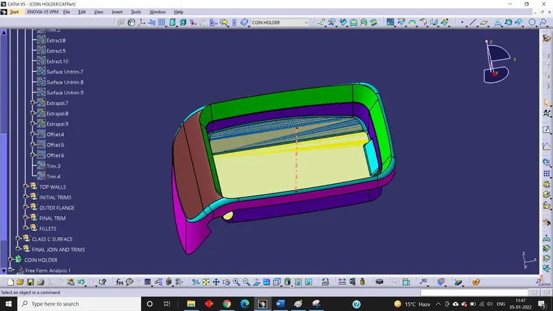
5. Creation of Class B Surface:
First of all, we divide the door arm rest into side walls, base, top walls and outer flange.
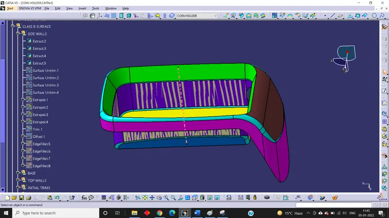
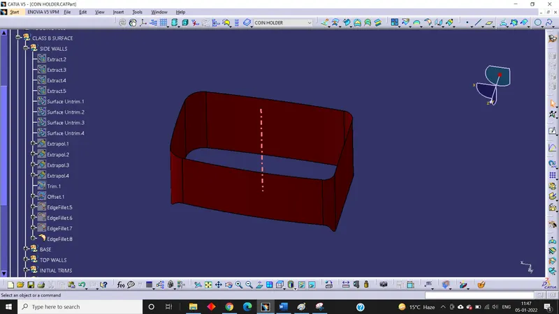
For Side Walls;
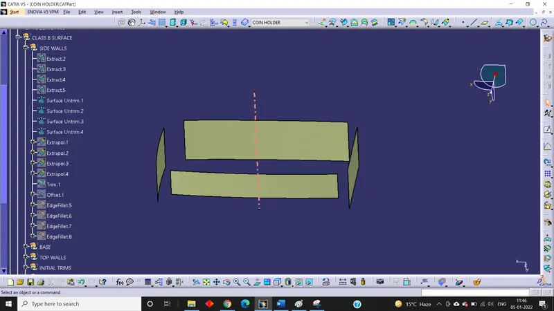
- Extract the side walls
- Untrim them
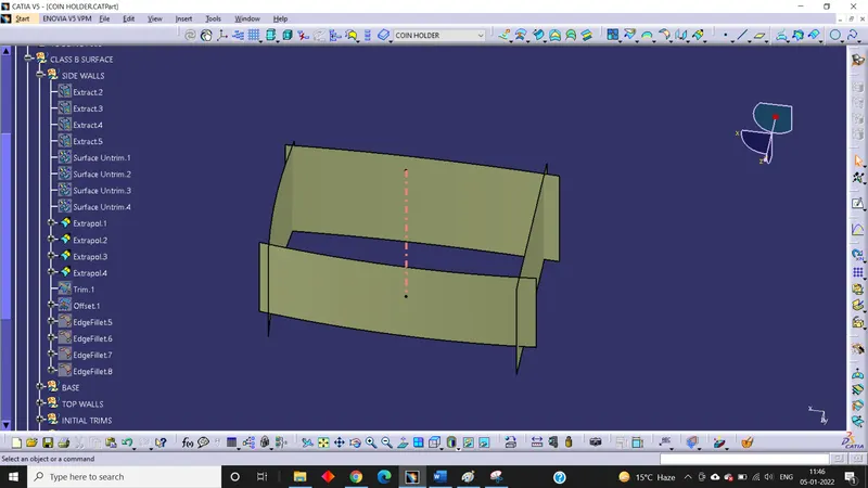
- Extrapolate them
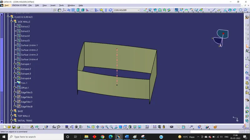
- Trim them
- Offset the trim outward by 2.5 mm
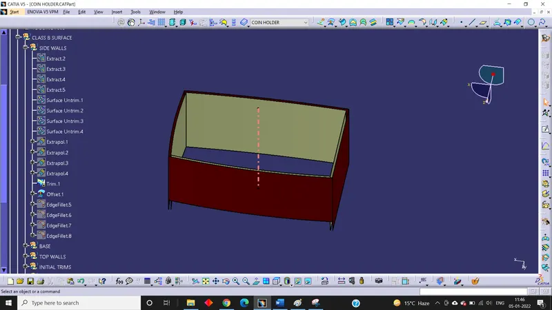
- Give the fillets considering the thickness value.
For Base Surface;
- Extract the base surface and the side surface connecting the base surface
- Untrim them
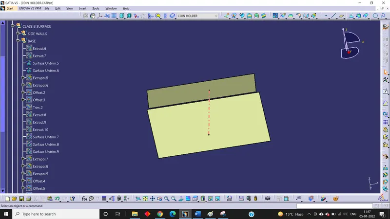
- Extrapolate them
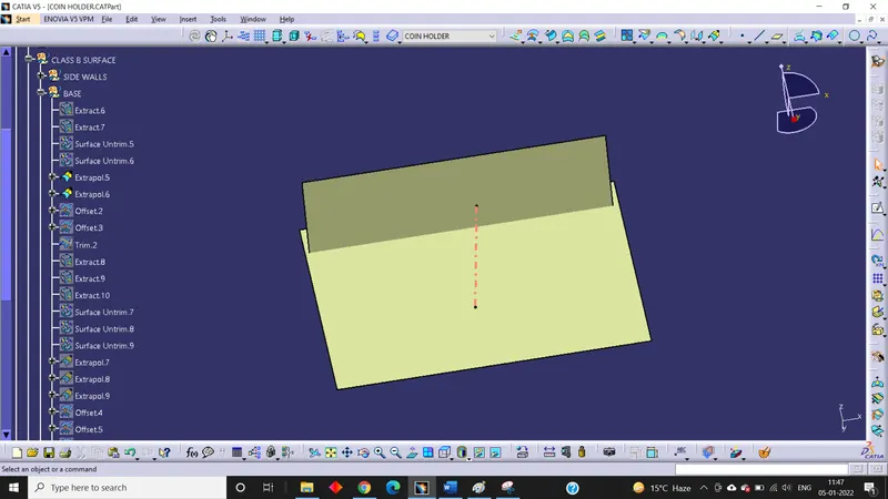
- Offset the surfaces in outward direction by 2.5 mm
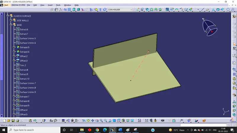
- After that trim them
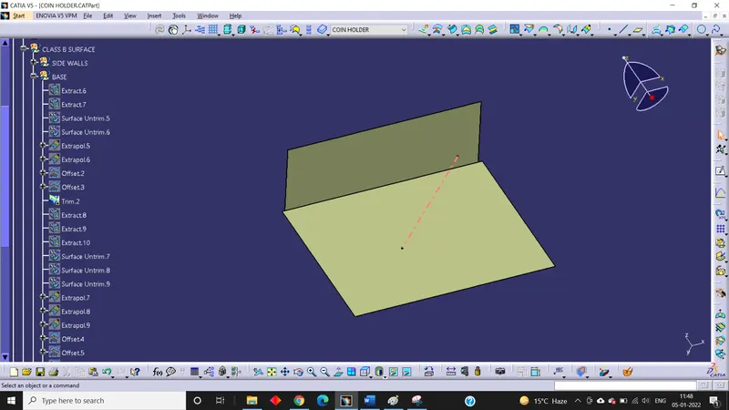
- Again, extract the surfaces of rib and do the same operation
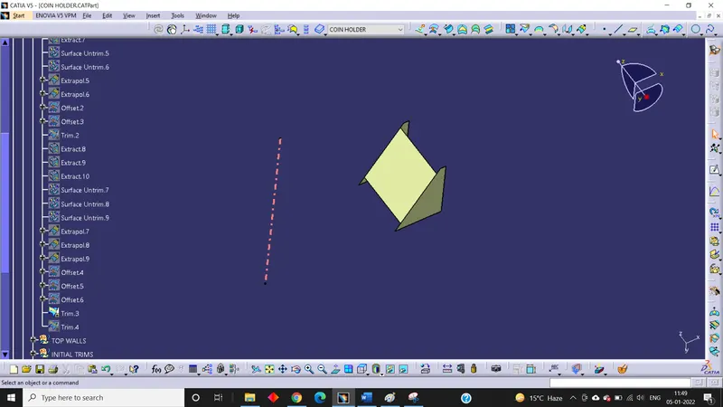
- After that trim the rib with the base surface
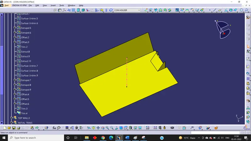
For Top Wall;
- Multiple extract the surface of the top walls ( fillets are not considered here as they are styling fillets)
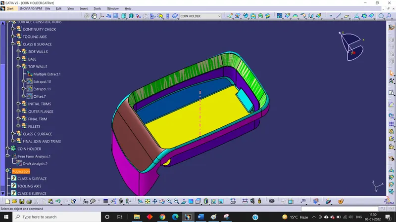
- Extrapolate in both directions
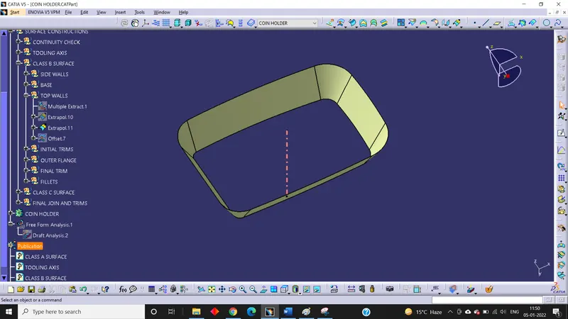
- Offset outward by 2.5 mm.
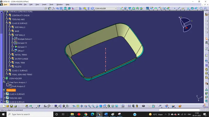
Initial Trims;
- First, we trim the base surface with the side walls
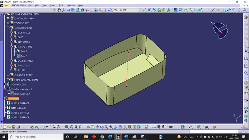
- Then the top wall is trimmed with the trim of base and side walls.
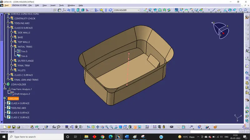
For Outer Flange;
- Multiple extract the outer flange
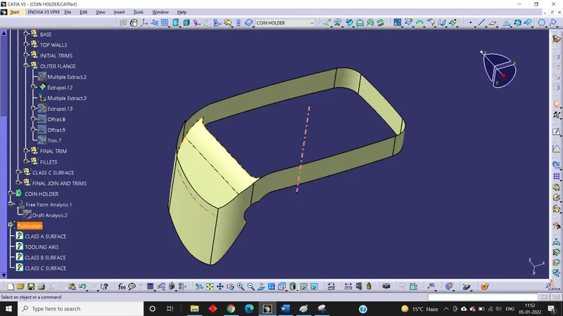
- Extrapolate them
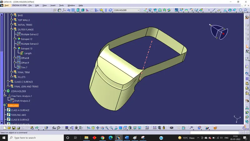
- Offset them downward by 2.5 mm
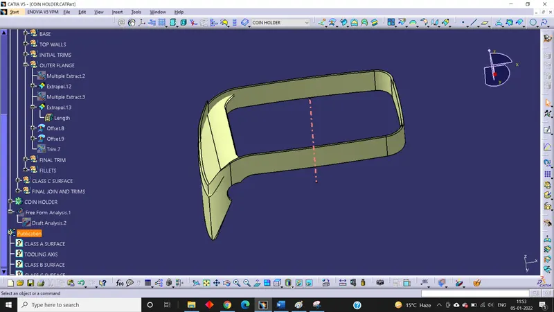
- Trim them
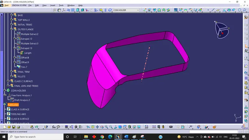
Final trims and fillets;
- At last trim the outer flange with the inner surface
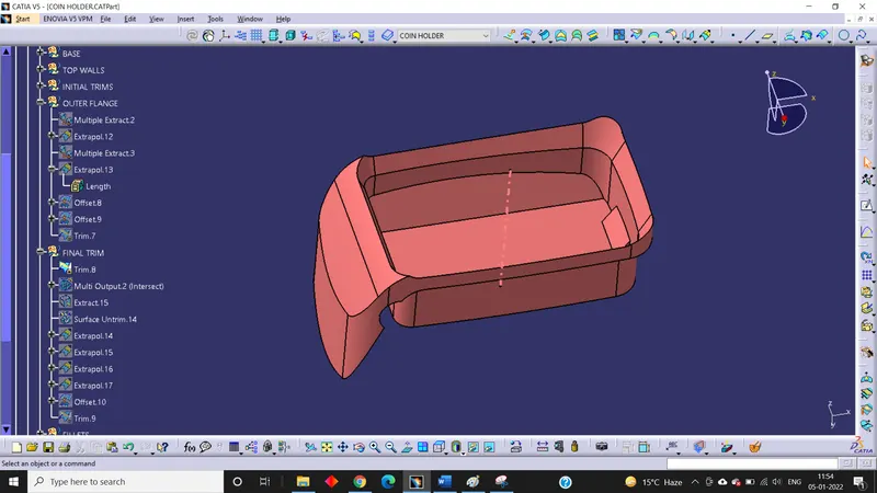
- Here we see the surface is crossing the Class A surface so, we extract the flat surface from Class A, extrapolate it, offset by 2.5 mm downward and then trim the surface
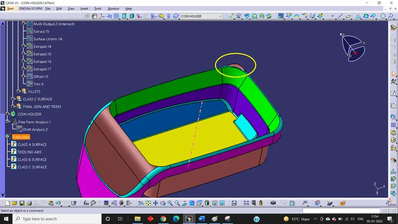
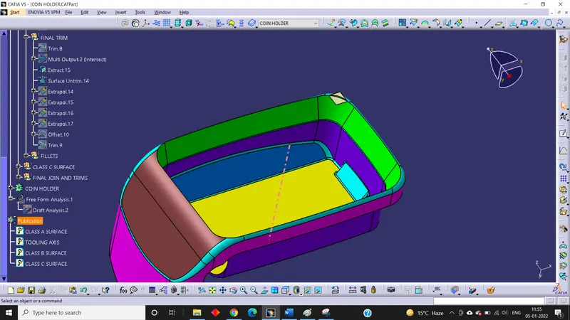
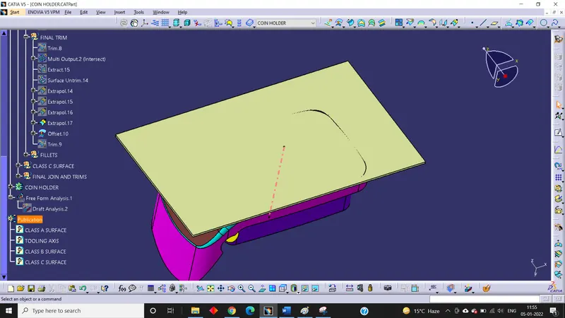
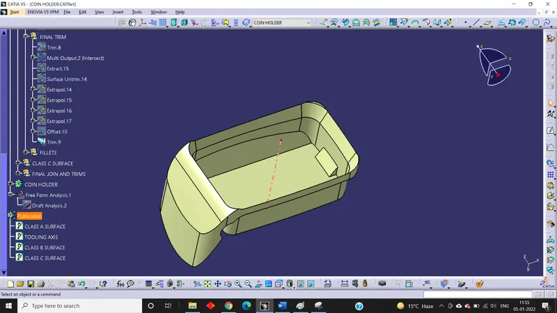
- After that apply fillets
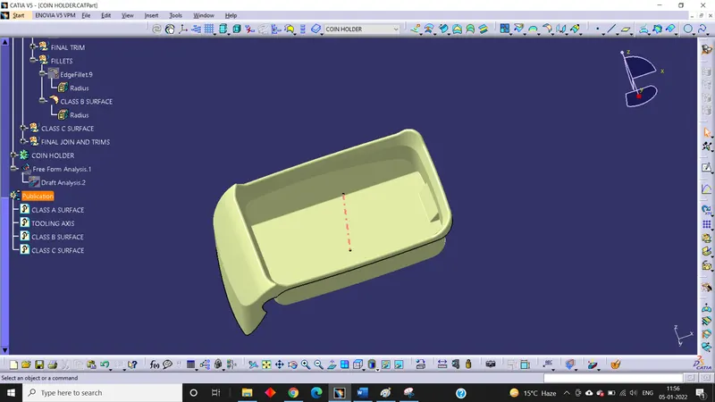
6. Creation of Class C Surface:
- First of all, multiple extract the outer boundary and the surface around it
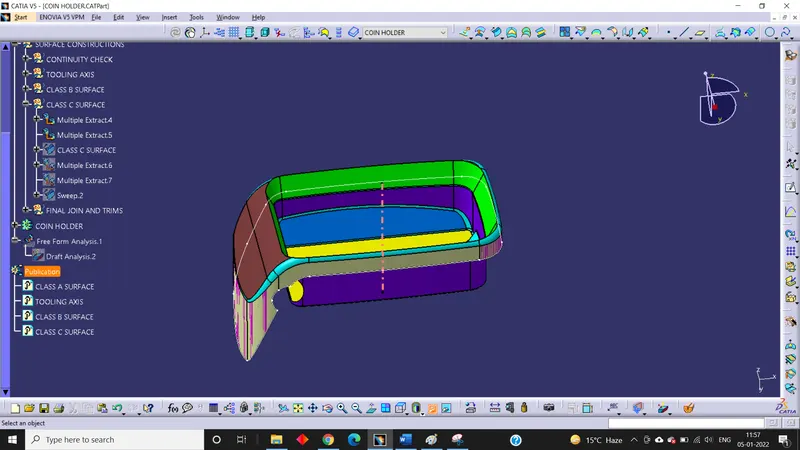
- After that, sweep the boundary perpendicular to the extracted surface
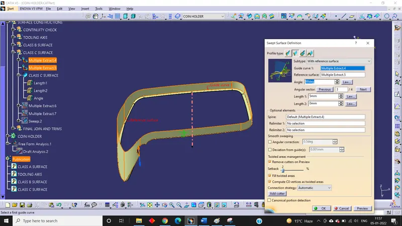
- The swept surface is our class c surface
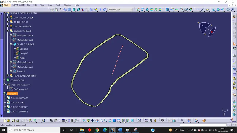
7. Solid Body Formation:
- Join the class C surface with class A surface.
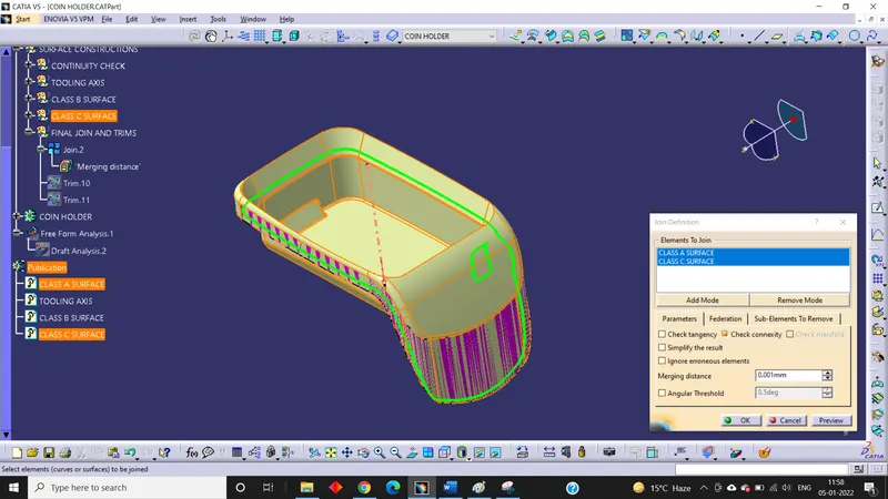
- Trim the B surface with the join created earlier.
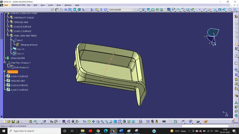
- Now we see that lower portion of the hole is not created so, we multiple extract the hole boundary and the surface around it and then sweep the boundary perpendicular to the extracted surface.
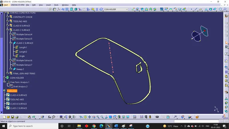
- After that trim the sweep with the join of class c surface and class a surface
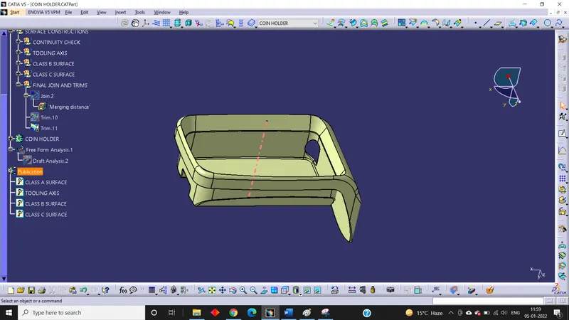
- Then use boundary command to check if there is any gap or not and we found that the model is fully closed.
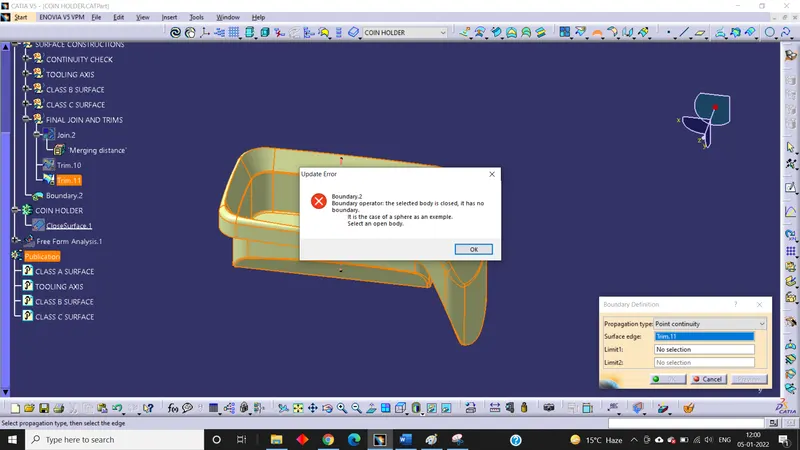
- Now go to the part workbench and close the part using close surface option.
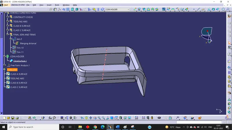
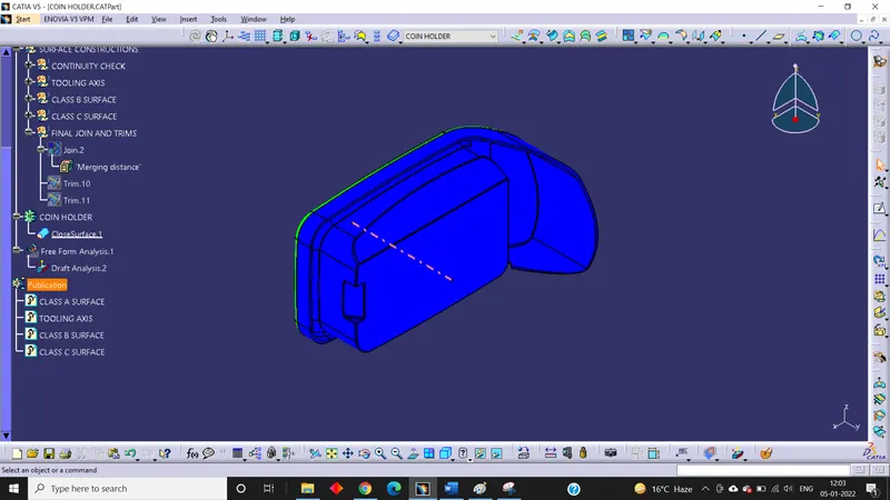
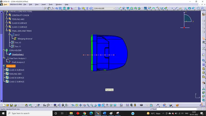
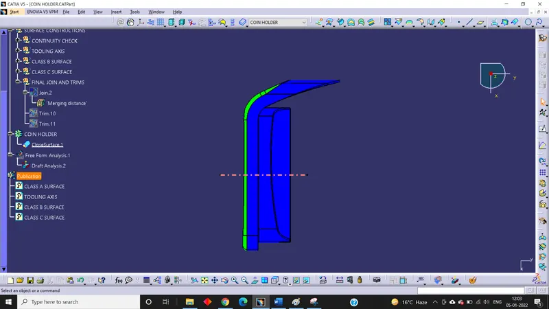
8. Final Draft Analysis for Solid Model:
First of all, change the view to Customize View Parameters and then check material mode selected and perform the same operation as done for Class A Surface while we did in doing draft analysis.
Isometric View:
Front View:
Side View:
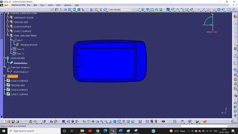
Top View:
3D View:
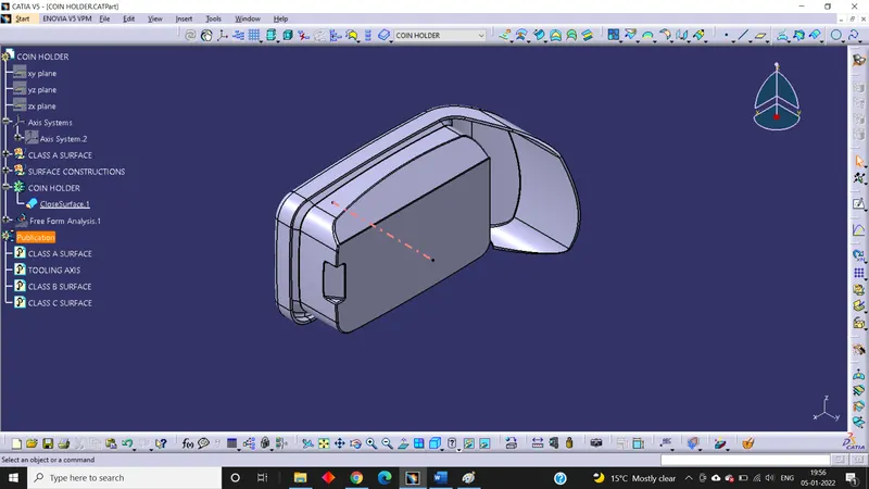
Isometric View:
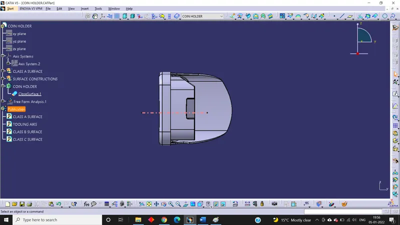
Front View:
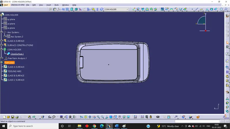
Side View:
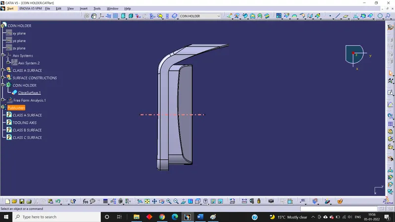
Top View:
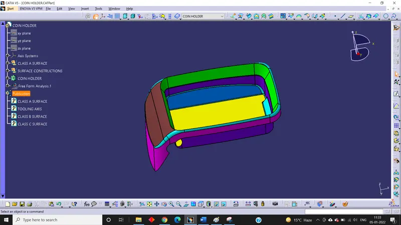
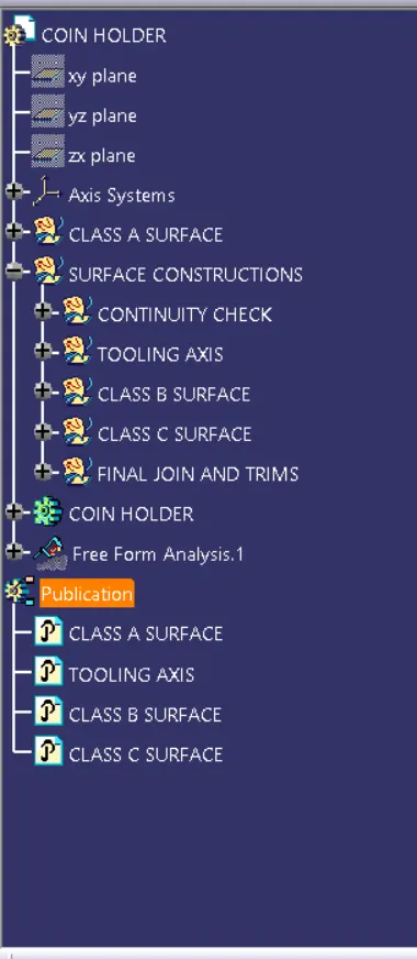
Tree Structure:
Conclusion:
From the given Class A Surface of Coin Holder, Class B Surface and Class C Surface were created to form a solid model and Draft analysis was done for both Class A Surface and the 3d model along with the tooling axis meeting the requirement of draft angle.