Week 8 - Challenge 4 - Coin Holder Design
COIN HOLDER
Aim: The main objective of this challenge is to create Class B and C surfaces from Class A surface, create a Tooling axis for the manufacturing aspect and finally Draft analysis.
Objective:
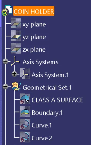
- To ensure proper tree structure is followed.
- Geometrical sets should have a proper name based on the sketch present inside of them it.
- All sketches should be as positioned sketch created under Geometrical set.
- Use the closed surface feature to make a solid surface.
- Take a thickness as 2.5mm
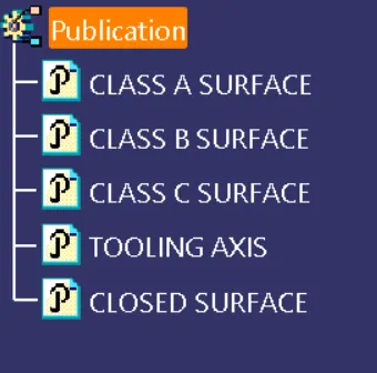
- Publish a Tooling axis, Class A, B, C surface
Procedure
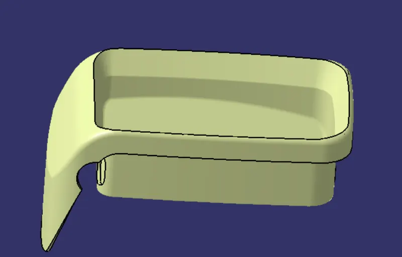
First import the class A surface of the coin holder model in Catia, Class A surface will be created by A designer.
CLASS A SURFACE
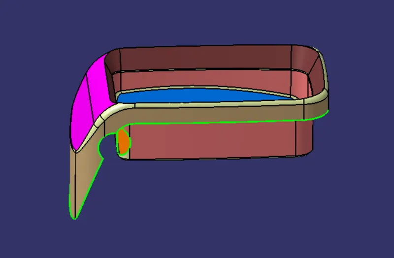
After importing to CATIA check the connectivity of class A surface by using a Boundary option, Ensure that there is no gap between the two surfaces.
TOOLING AXIS
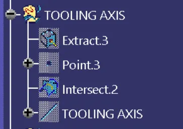
The tooling axis is the direction in which the mold opens or the core cavity opens. By providing tooling axis to components where we can also do a draft analysis of the components. Draft analysis is performed on the components where the ejection of materials happens after the material is made inside the tools. Normally to create a tooling axis if the model has a hole it will be consider as a primary stage to create an axis, Extract the base surface to create an axis, create a point at the center of the surface by using a point to point create an Axis.
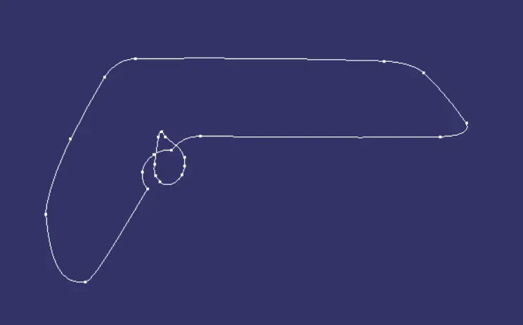
For the tooling axis, we first inspect by taking a section and then decide which direction would be better for the tool axis. then we create an axis system then we insert the surface A with YZ plane.
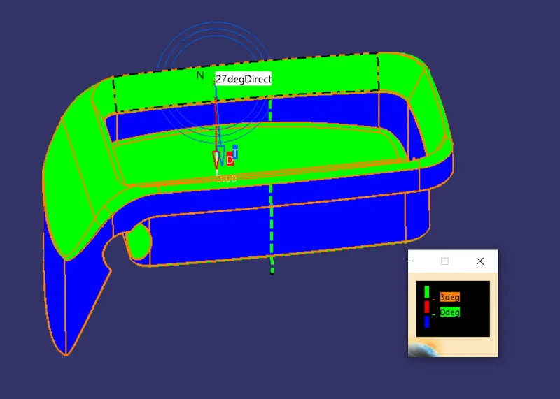
with intersection option, we got that in the class A surface side walls are parallel with the vertical axis but the angle is 0degree angle between them, But since it is Class A surface we need to proceed with same class A surface only here we do not have an authority to change the class A surface design. so we need to do draft and design the model from class A surface only.
Here we need to inform for Class A surface team to provide a Minimum draft angle of 3 degrees for the class A surface, If the case draft angle is 0 then it could be a problem in the manufacturing area part will be wear and get some scratch, friction while ejecting a part.
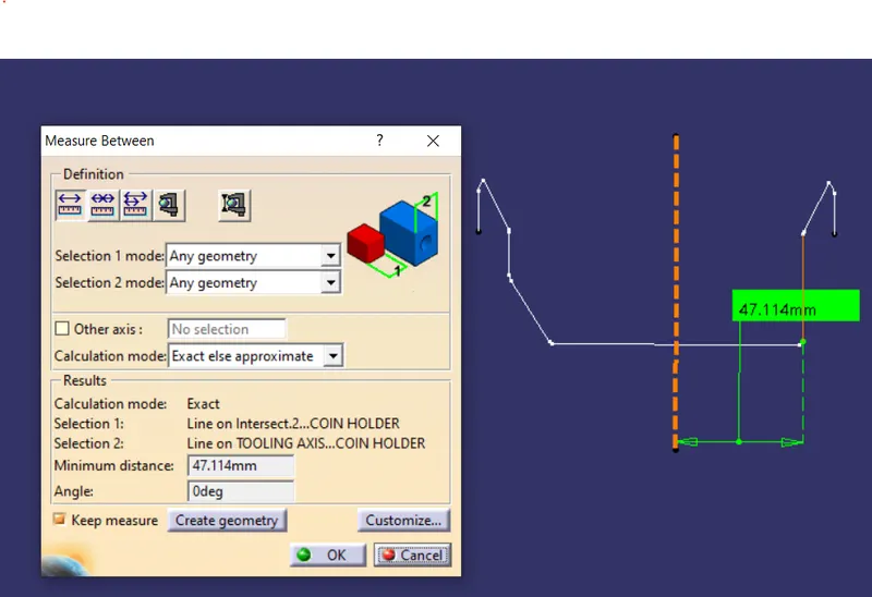
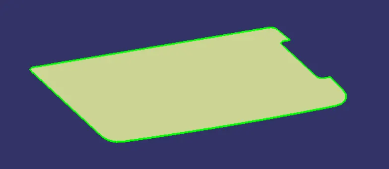
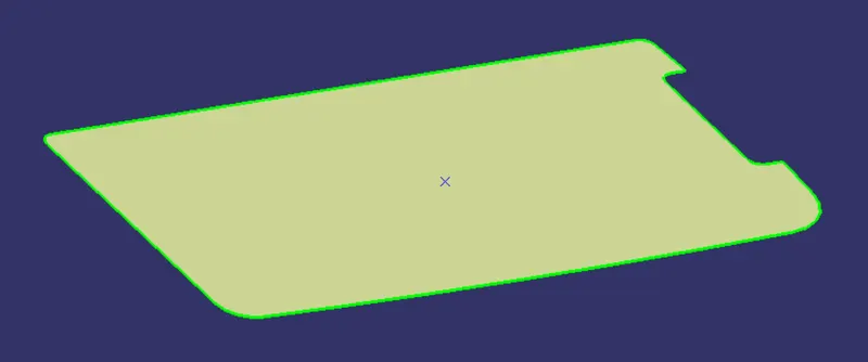
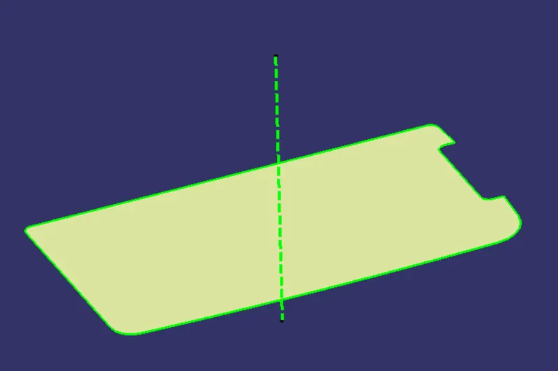
Draft analysis for CLASS A SURFACE
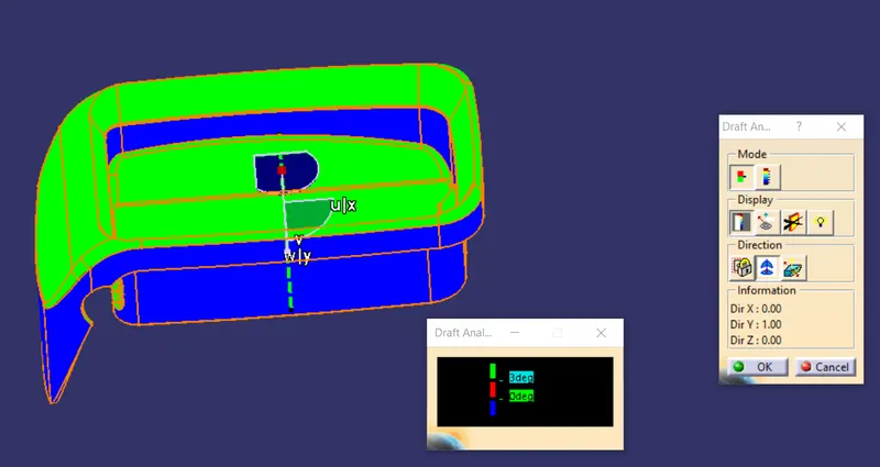
After selecting a tooling axis we need to do a draft analysis, before drafting we have to make sure that in the view mode it is selected for the materials. After selecting then need to go for the Insert option select the Analysis tool in that Feature draft analysis.
Select the compass then insert the compass on the tooling axis, then lock the compass after selecting the components anywhere it highlights the colour indicates as green has draft angle has a minimum of 3 degrees.
By using a running point option to check the angle of the components, we can even modify the colour according to our preference.
Class B surface
Since these are complex components we separate them by applying some colors to the surface for our ease and then creating a class B surface.
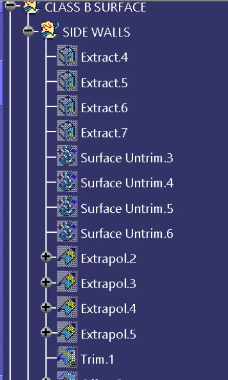
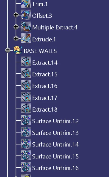
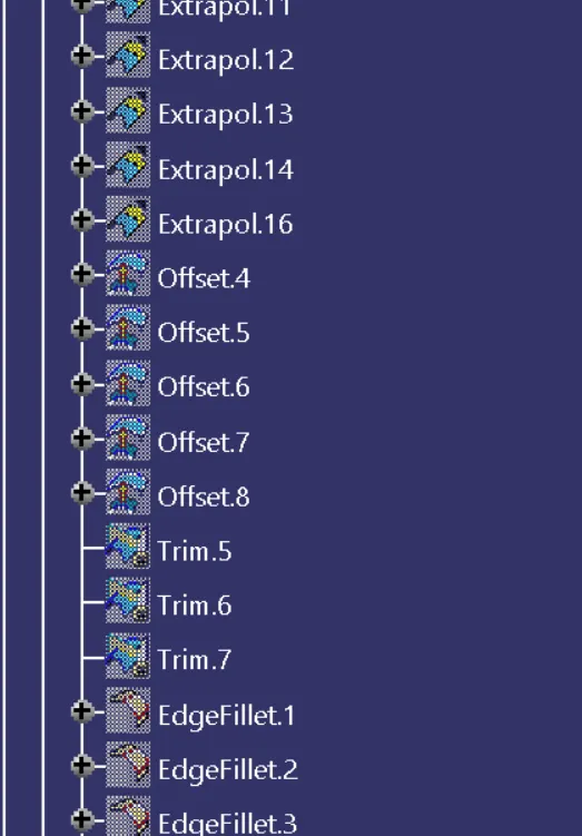
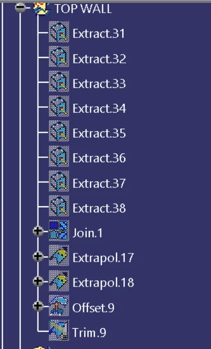
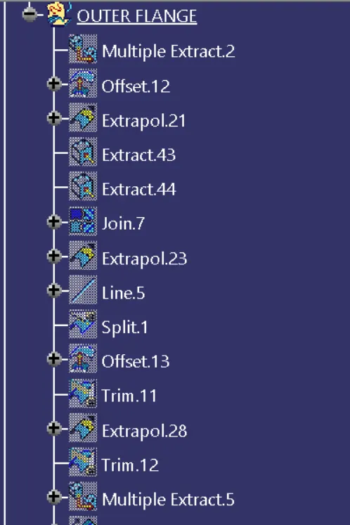
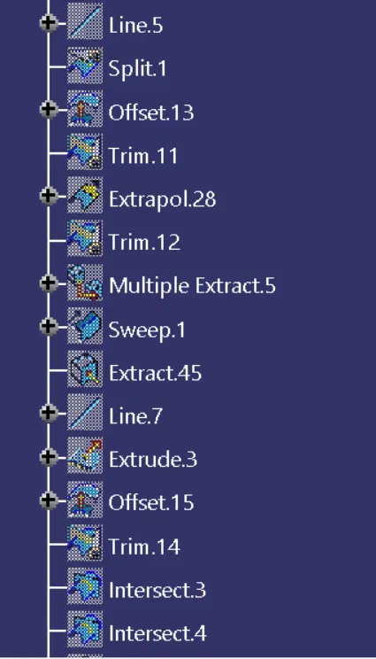
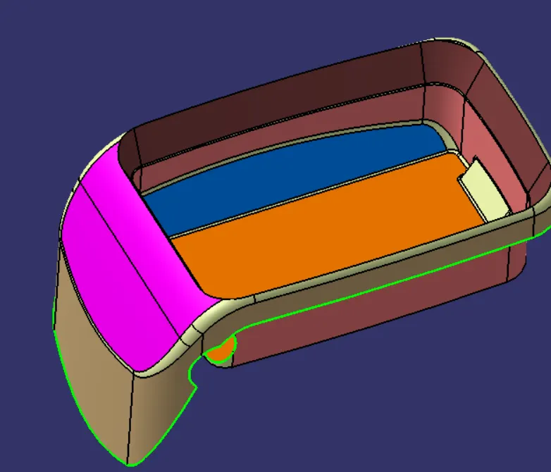
We start creating the class B surface for that apply the offset for all the flat surfaces to 2.5mm and then we use to extract the flat surface use the untrim option for the surface and then extrapolate the to extend the surface. we do this for all the surfaces to separate sections we created and we trim all the sections together.
Finally, apply the edge fillet to the corners.
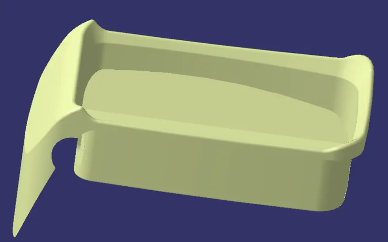
CLASS C SURFACE
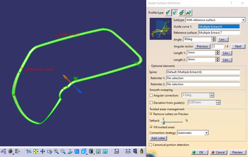
We first extract the edges from the class A surface with the help of which we create the path for a sweep for the class Csrface and even extract the adjacent surface to use it as a reference plane
So we select the sweep tool and in that for profile type will be as with reference surface for guide curve select the extract the boundary edges and reference surface as extract adjacent surface as a reference, select the sweep angle as 90 degrees as horizontal.
After creating class C surface, joined with a class A surface finally this will trim with class B surface as a final components
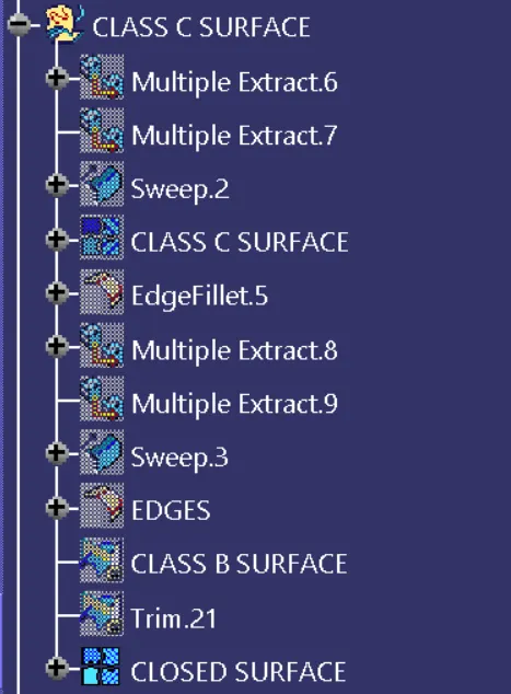

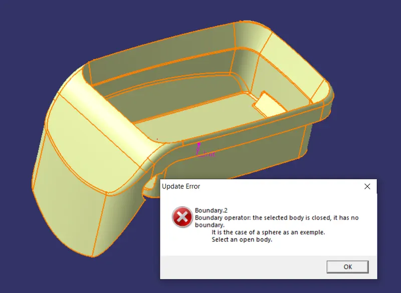
After creating a class C surface, joined with a class A surface finally this will trim with a class B surface as a final component, to check that use the boundary option to check the selected body is closed or not.
CLOSED SURFACE
After we go to the part design workbench and use the closed surface tool to create a solid body of the closed surface components. we can also do a draft analysis on the solid body also.
PUBLICATION
Draft analysis for solid body

Views
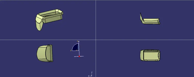
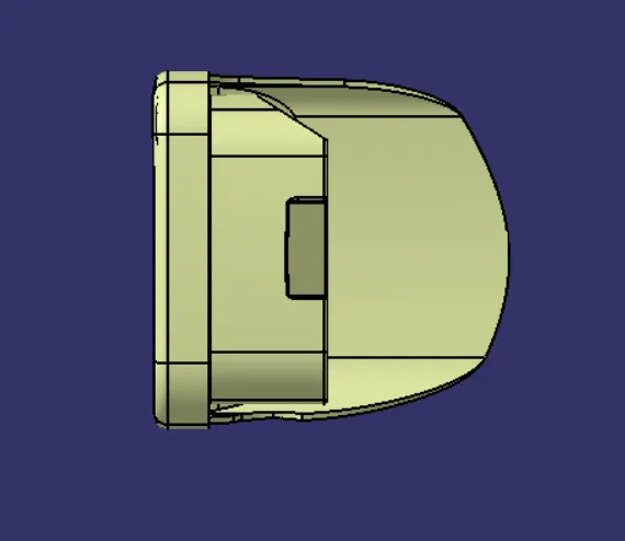
FRONT VIEW
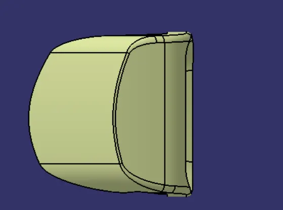
BACK VIEW
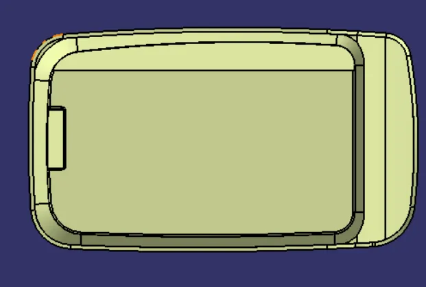
RIGHT VIEW
Conclusion
with the help of class A surface created a class B and class C surface also draft analysis is done for the solid body.