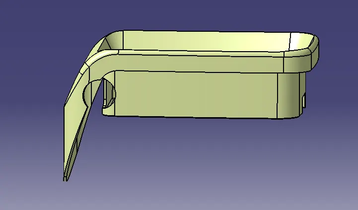
Week 8 - Challenge 4 - Coin Holder Design
Aim :- Create the Coin Holder Plastic component through the given Class-A surface. the tooling axis for the given Class-A Surface is created meeting the requirements of the draft angle and at the end perform the Draft analysis on the model. Thickness of the component to be 2.5 mm
Procedure :-
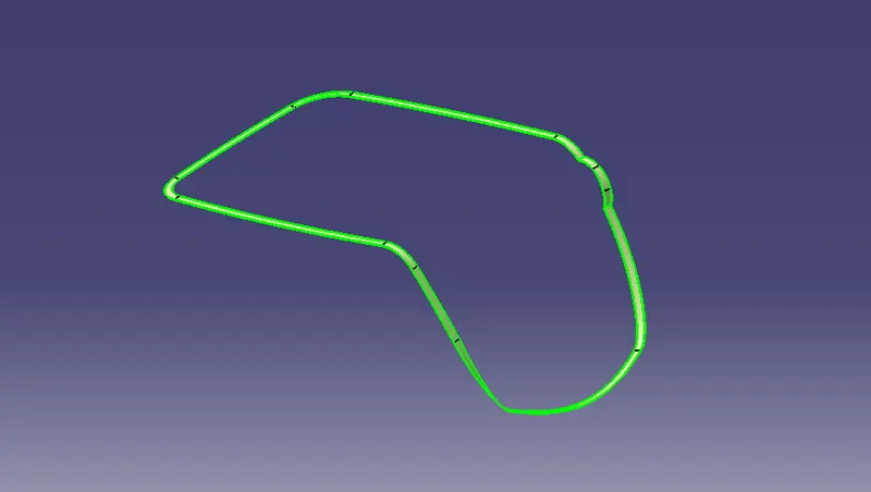
- the given surface is considered as Class-A surface. check for the gaps in between the surfaces by using boundry option, make sure no gaps are present.
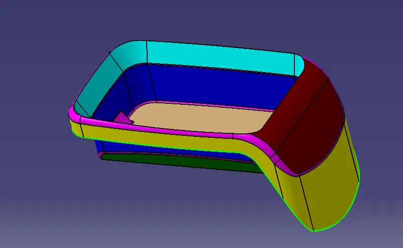
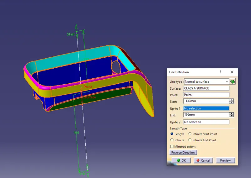
- now to create a Tooling Axis , visually inspect the model to finalise the draft direction and create the tooling axis according to it. consider the side walls for reference. as the walls are 90 degrees and have 0 degree draft angle. consider a line normal to the surface by creating a point in the middle and rename it as Tooling Axis.
- the alternate way of creating using the bisecting lines method is not required.
- insert separate geometrical set for the tooling axis creation.
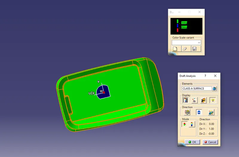
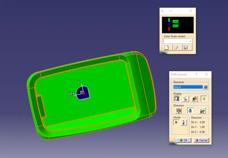
- now perform the Draft Analysis to the given Class-A surface. Goto- Insert- Analysis- Feature draft analysis. drag the compass to the tooling axis and select the surface. the view from the draft direction should be Green in colour.
- now the Class-B surface is created with the reference from the given Class-a surface, insert a geometrical set and rename it for the class-B creation.
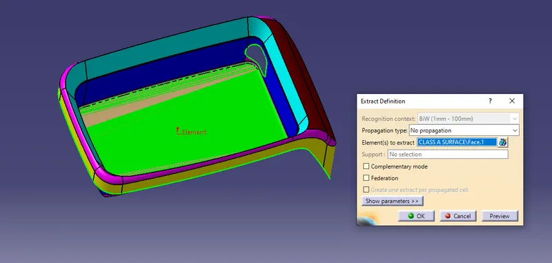
- extract the side walls of the bin section and untrim the surfaces.
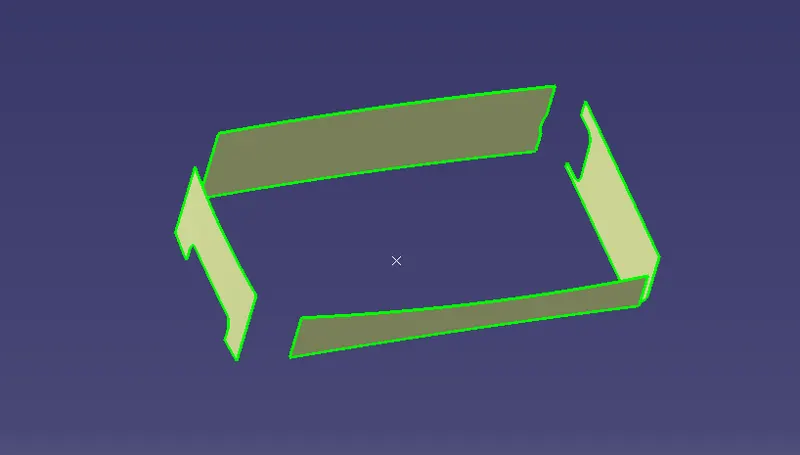
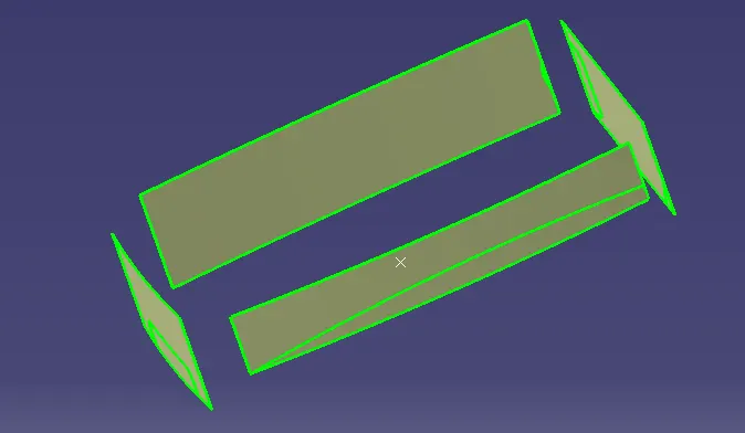
- hide the extracted surface and extrapolate the untrimmed surface . extrapolate using th epoint continuity option to make sure they intersect with each other
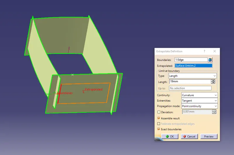
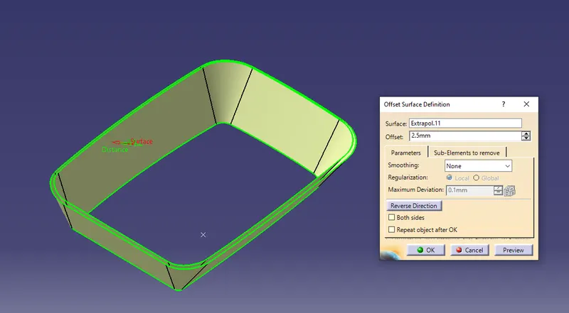
- off-set the walls with 2.5mm as thickness away from the class-A surface. trim the surfaces according to the class-A
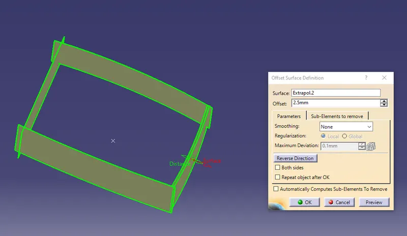
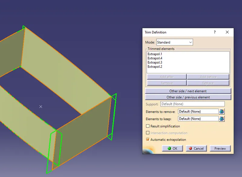
- similarly extract the base and angles side surface from the given class-A and untrim the surface. hide the extracted surface and extrapolate them to intersect, then off-set to 2.5mm and trim the extra surface.
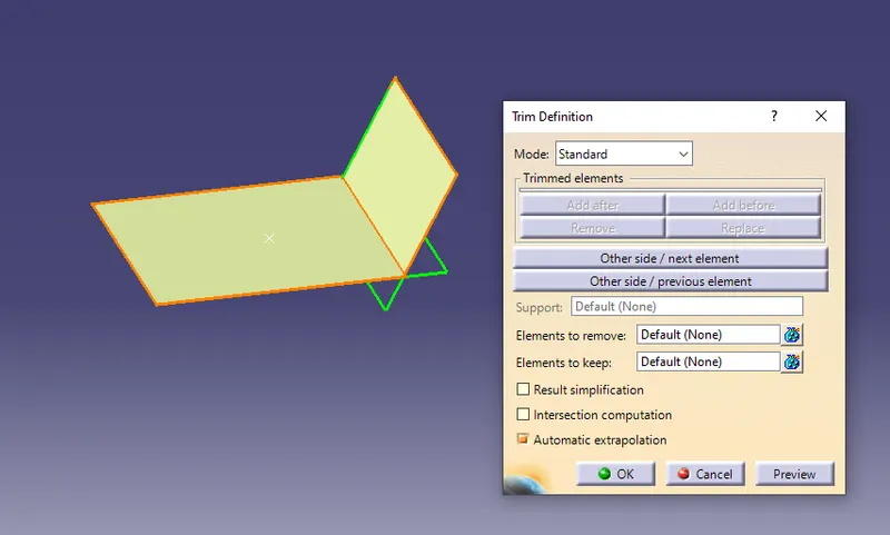
- now unhide the side walls section and trim the base with the side walls. extrapolate when ever there is no intersection of surfaces during the trim .
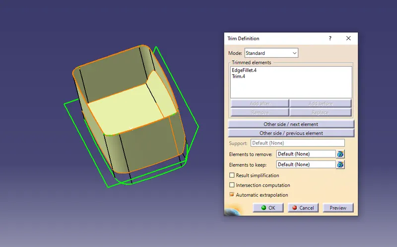
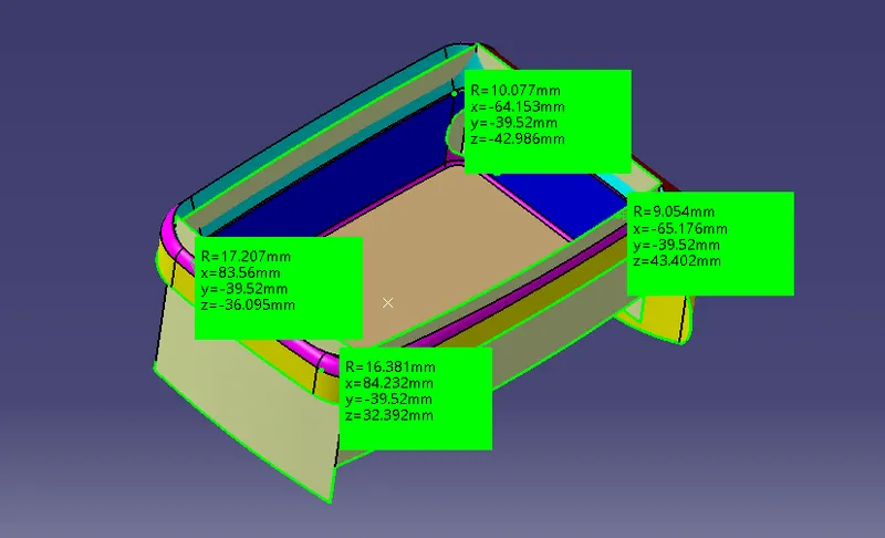
- now, measure the fillets of the side walls section individually. extract the surface and untrim to exactly measure the radius of the fillets.
- for the fillets add the thickness of the off-set to precisely create the fillet surface on the B-surface.
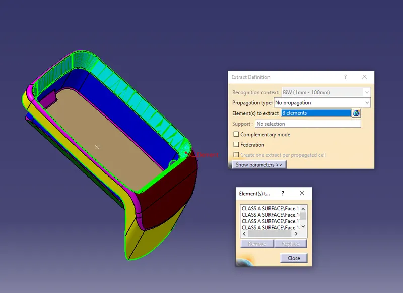
- extract the upper walls of the component using multiple extract options and do not untrim them as the angled features will be deformed. hence extrapolate them using curvature option and offset the inside the class-A surface.
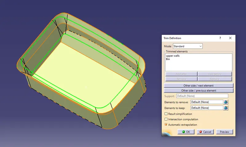
- now trim the upper walls with the bin section.
- compare the created surfaces with the class -A surface using the cut-section option to easily visualise the difference between the two surfaces.
- now add the fillets at the required loactions by measuring the radius on the class-A . now extract the other surfaces on the sides using multiple extract option.
- similarly extrapolate them and off-set to 2.5 mm towards the class-A . the other part of the surface is extracted individually using the curvature option and extrapolate to intersect with the bin section .
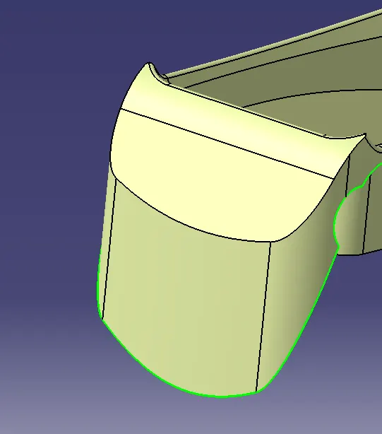
- trim the surfaces according to the required form using the class-A as reference. Class-B surface is created.
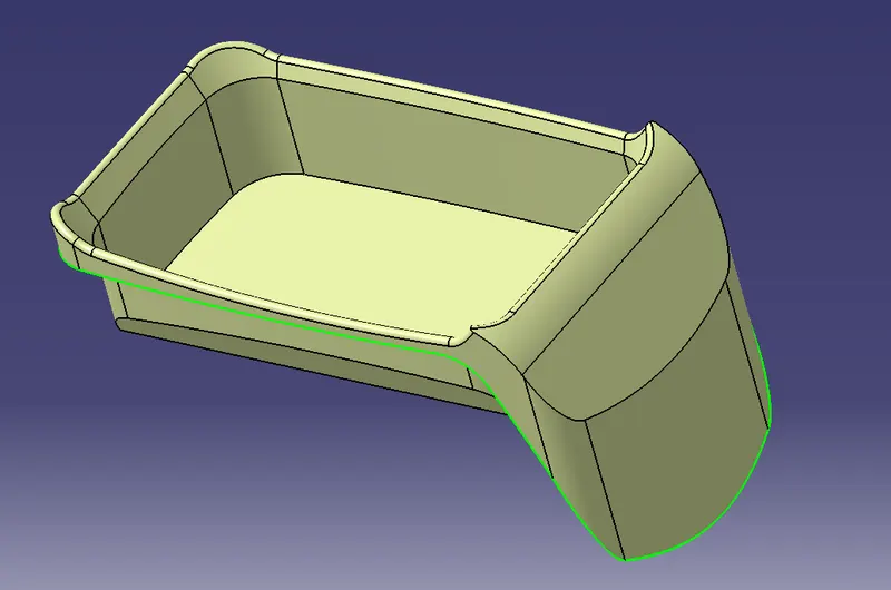
- there are some features in the bin section of the component.. a hole and an angled projection. they are create on the class-B .., in order to create the hole. extract the the boundries of th ehole of class-A surface also multiple extract the surfaces around the hole(guide). use sweep option with reference to the surface select the guiding curve. put the angle as 90 degrees and length as >2.5 mm in the direction according to the classB.
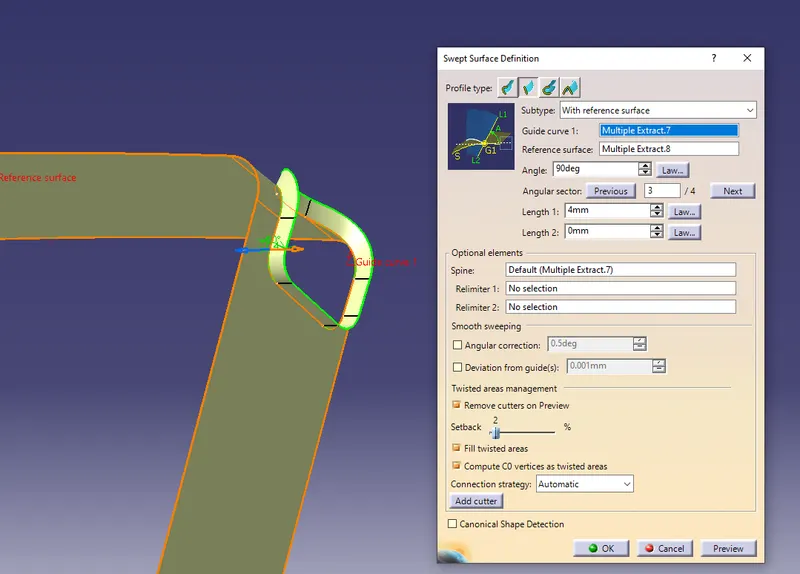
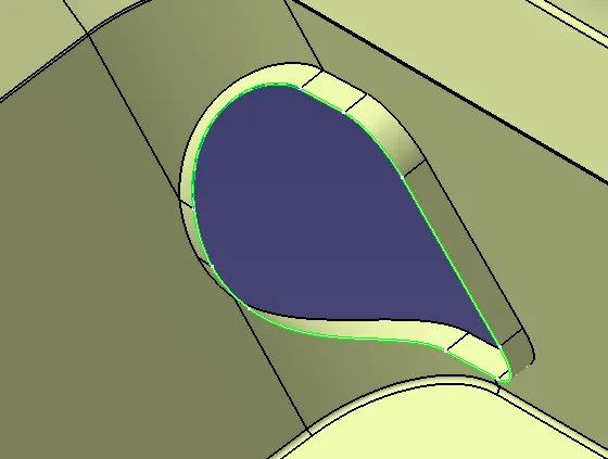
- trim the hole surface with the side walls of the bin section to get the exact surfaces required. now similarly multiple extract the surfaces of the angled projection and untrim them, hide the extracted surfaces. extrapolate them to intersect them with eachother. off-set the surfaces to 2.5mm and trim them with the class-B surface.
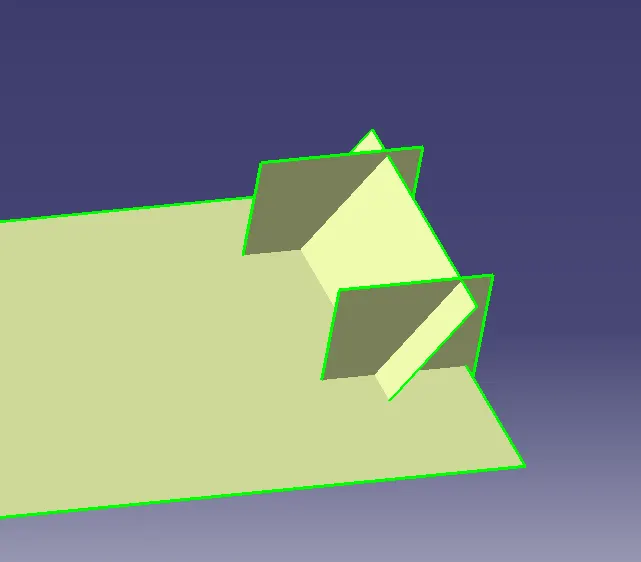
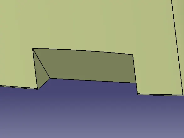
- fillet the edges of the projections with 0.5mm as min radius. and add the projection with the other surfaces.
- now a Class-B surface is created from the reference with the Class-A surface.
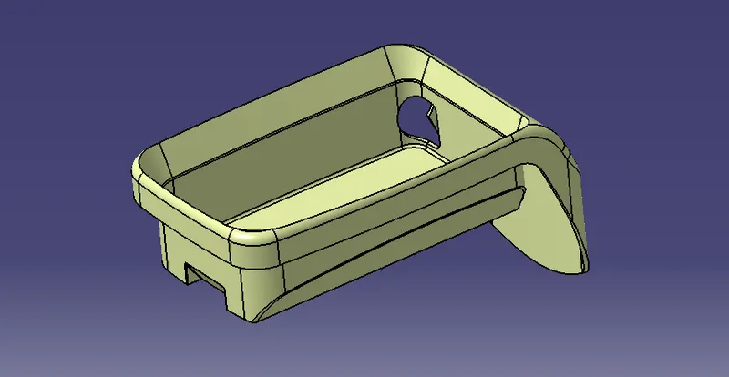
- now to create the class-C surface, as the class-A is having curves and not in a proper direction. extract the boundries of class-A using multiple extract and tangent continuity. similarly extract the surfaces touching the curve which acts as shape guidance.
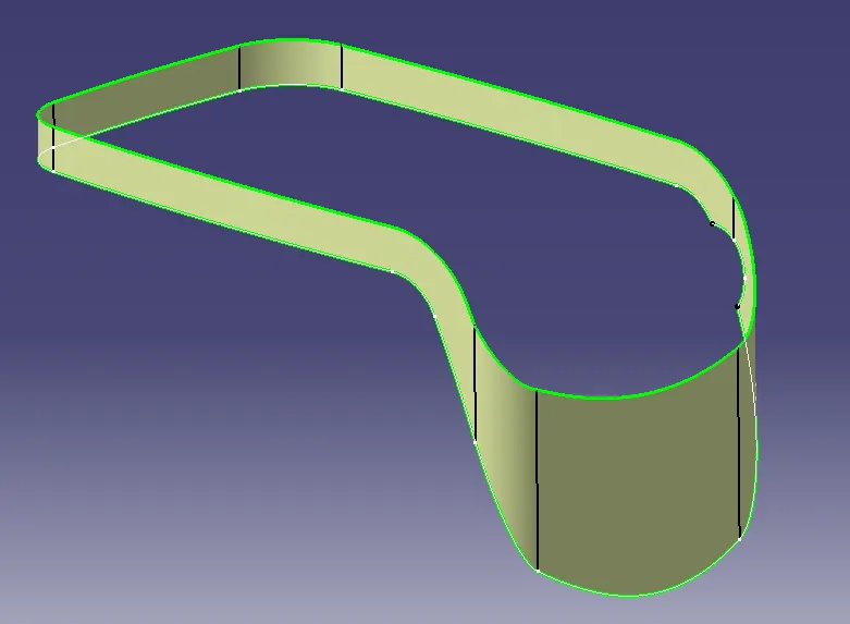
- now using the sweep option and with surface reference. keping the angle 90 degrees and length > 2.5mm selecting the direction of sweep towards the class-B create the surface for class-C.
- trim the class-C with the class-B surfaces to get the exact shape.
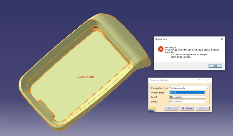
- now join the surfaces A,B&C together as a trim. to make sure the surfaces are joined and no gaps in between click on boundry option and select the trim surface, since the surfaces are closed it shows the warning error.
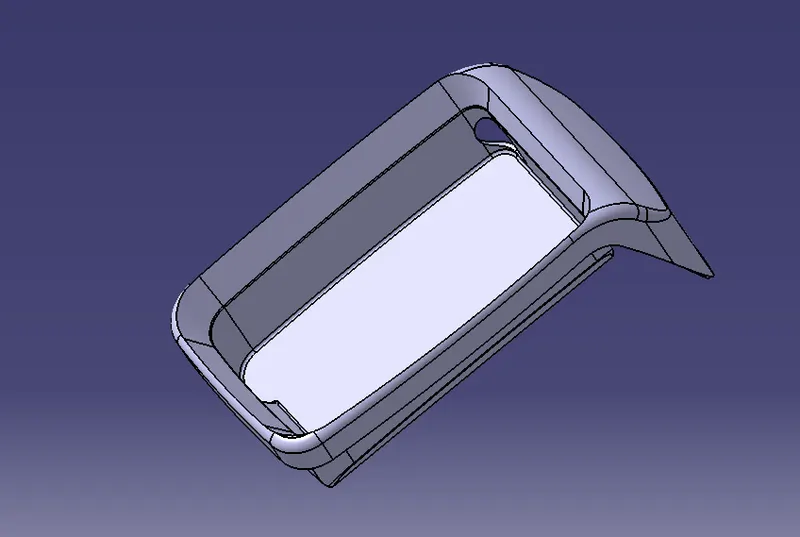
- now to create a solid body out of the surfaces created.. Goto mechanical designs- Part design and use fill surfaces to create the solid body out of the surfaces.
- perform the Draft analysis on the created surface.. unhide the tooling axis Goto- Insert - Analysis - feature draft analysis . place the compass on the tooling axis. set the draft angle to 2.9mm and check for the draft angle.
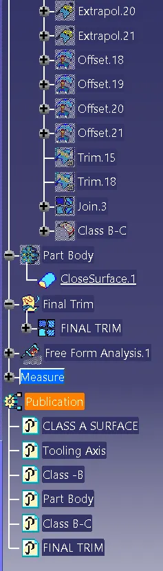
- insert separate geometrical sets for every class surfaces created in order to differentiate them easily. also publish the tooling-axis, class-A , B & C surfcaes , draft analysis of Class-A and the closed surfaces created.
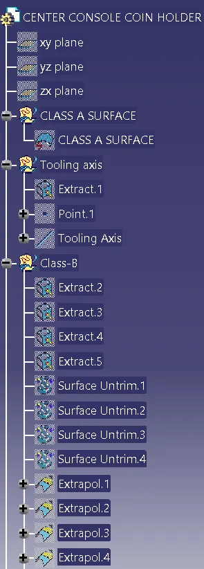
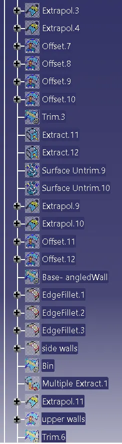
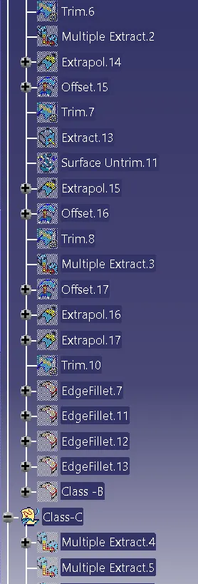
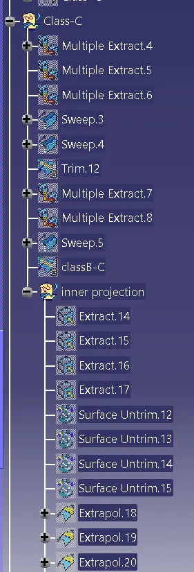
Model Tree -
Result :-
Isometric view -
Front view -
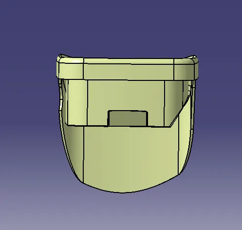
Side view -