Week 8 - Challenge 4 - Coin Holder Design
Aim:
To create the Coin Holder Plastic component through the given Class-A surface. To begin with, the tooling axis for the given Class-A Surface should be created meeting the requirements of the draft angle and at the end perform the Draft analysis on the model.
Take the Thickness of the component to be 2.5 mm
Objective:
- To design coin holders as per automotive OEM Standard.
- Create B Class and C Class and tooling axes.
- Convert close loss the surface into a solid body and provide the thickness of 2.5mm.
- Performing draft analysis to verify the creation of the Tooling axis and C Class surface.
Software:
- CATIA V5 (Generative Shape Design)
Design Methodology with images:
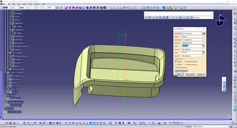
Procedure for creating Tooling Axis:
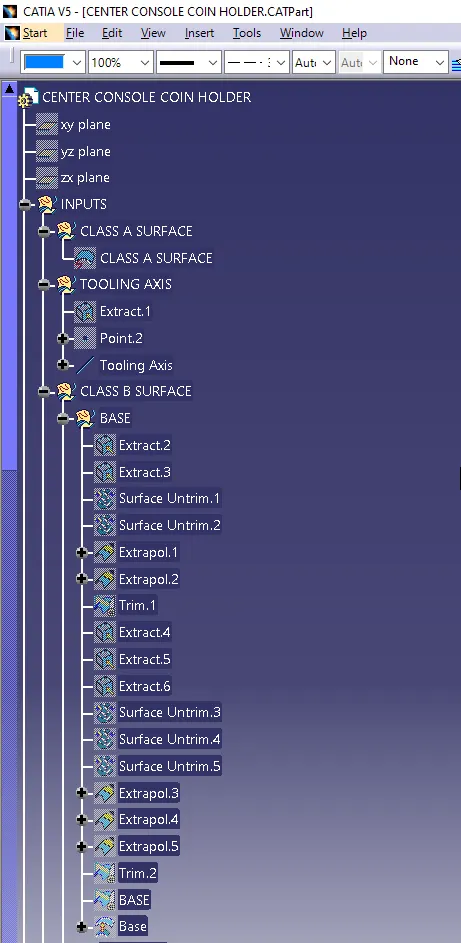
- Intersect the model with the plane perpendicular or to an axis system.
- Extend the lines which are perpendicular to the plane.
- Again intersect the model with another plane and extend the lines perpendicular to it.
- Create a bisecting line by bisecting the option in Line definition.
- Rename it as Tooling Axis.
Procedure for creating B Class surafce:
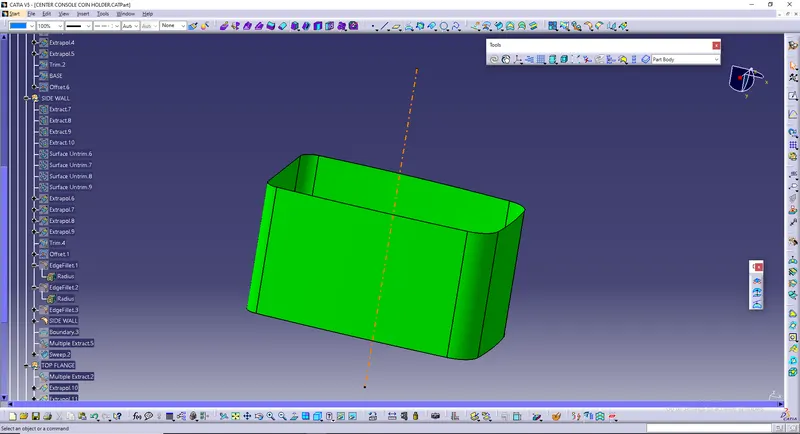
Side Walls:
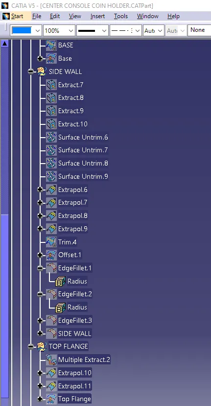
- Extract the side walls with no propagation in the extract option.
- Untrim them.
- Extrapolate the walls with point continuity of distance 20mm.
- Trim the walls to get the required shape.
- Offset those trimmed walls with thickness value.
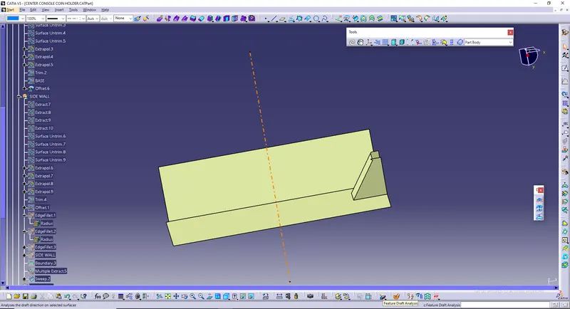
Base:
- Extract the surfaces separately and untrim them.
- Extrapolate the surfaces with required distances.
- Offset them with thickness value.
- Trim them for required shape.
- Measure the fillets, calculate it and create fillets.
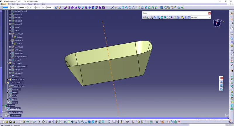
Top Flange:
- Extract the surfaces separately and untrim them.
- Extrapolate the surfaces with required distances.
- Offset them with thickness value.
- Trim them for required shape.
- Measure the fillets, calculate it and create fillets.
Outer Flange:
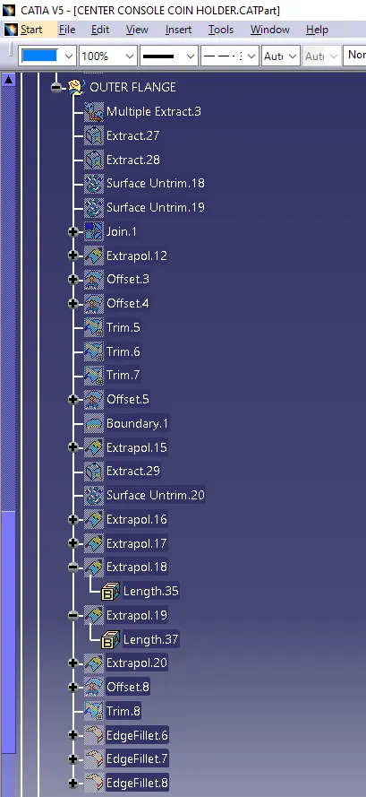
- Extract the surfaces separately and untrim them.
- Extrapolate the surfaces with required distances.
- Offset them with thickness value.
- Trim them for required shape.
- Measure the fillets, calculate it and create fillets.
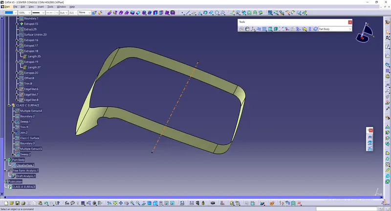
Procedure for creating Class C Surface:
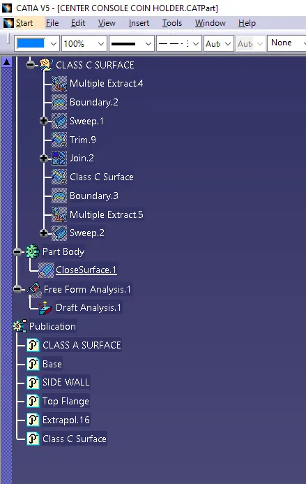
- Get the boundary lines of Class A surface separately.
- Smooth the curves with a smooth option as boundary lines have a lot of vertices.
- Sweep the curves with the tooling axis as direction in the Sweep option.
- As both lines do not intersect, extrapolate them with a certain distance.
- Trim the surfaces.
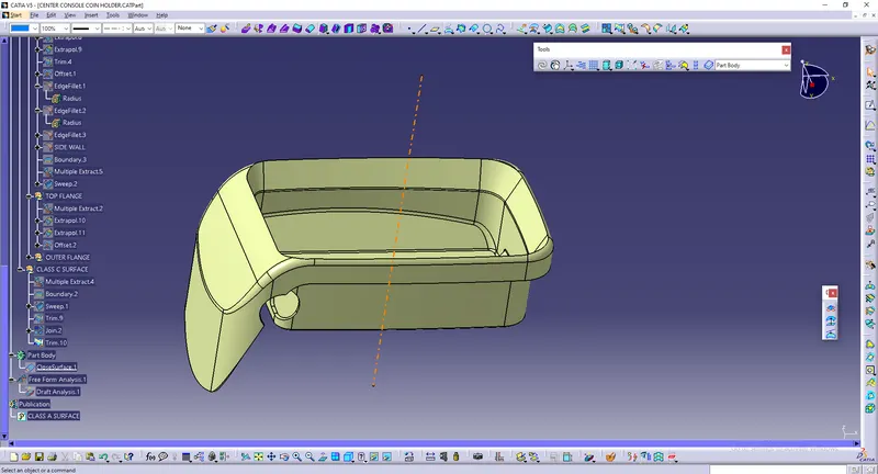
Procedure for creating Closed Body:
- Join the Class A and Class C surfaces.
- Trim those joined surfaces with Class B surfaces.
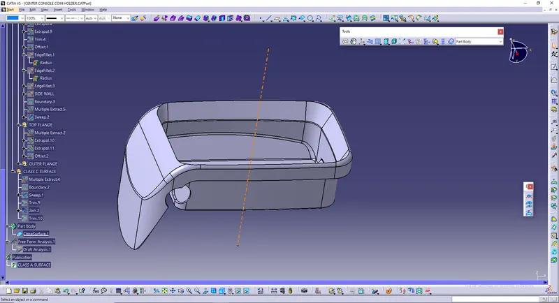
- Go to Part Design and insert a Body.
- Create a closed surface.
Procedure for creating Draft Analysis:
- Go to the Insert menu and select the Analysis option.
- Select Feature Draft Analysis.
- Select the Material option and select the surface.
- Drag the compass and place it on the tooling axis.
- Make sure that the top surface is in green colour as draft angle should not exceed 3deg.
- Click on Okay after confirming the model.
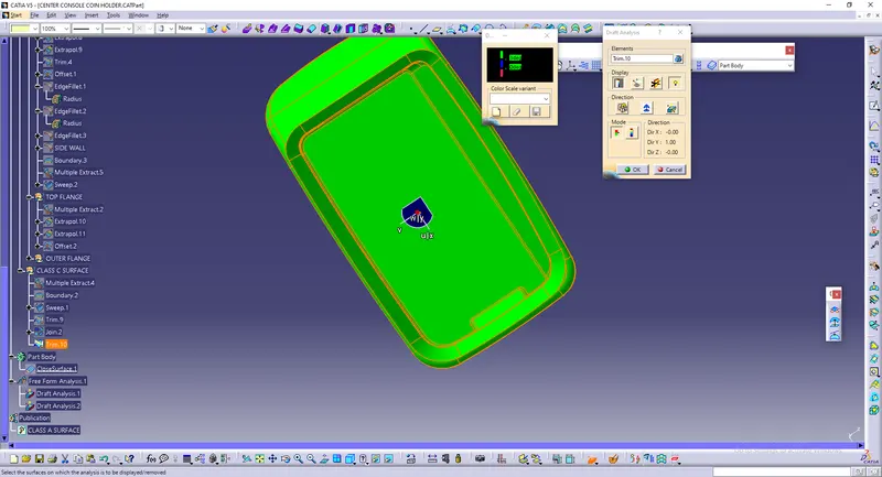
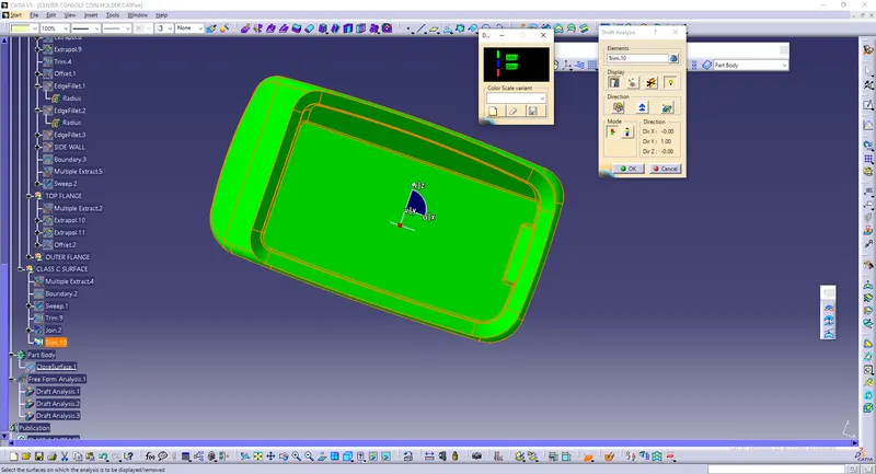
- Screenshots of the solid model with the proper color code of the draft angle in various orientations (Isometric, Front, Side, and Top View)
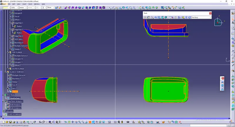
Tree Structure: