Week 8 - Challenge 4 - Coin Holder Design
Procedure To Create Class-B & Class-C & Draft Analysis of Coin Holder
Step -1: - check the Class-A surface for all joints are connected properly if any surfaces are required to join use the join tool in Join- Healing toolbar or use the Boundary command in the Extract toolbar.
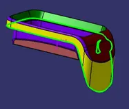
Step -2: - Check component in all 3 Axis the component. In which direction component can clear all the features in the tooling axis. In my case, according to the class-A, I tool Y-axis is my tooling axis. Due to the component side walls are having 900with respect to the base I took the center line perpendicular to the plane. That covers all the sides of the component. Insert all the tooling axis features into a geometrical set and name Tooling Axis.
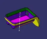
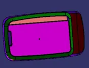
Step -3: - then the next step starts with creating the B-surface for the required component for that insert a new geometrical set and name as B-surface and insert another geometric set and name as Sidewalls and extract the side walls of the component and untrim the extracted surfaces and extrapolate the walls until it connects with the corner surface in my case I took 20mm as the extrapolate and trim all the unwanted surface at the final will get a closed surface and offset the surface at 2.5mm outward direction and add required fillets for the offset surface .
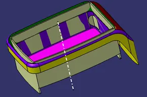
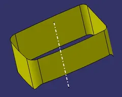
Step -4: - the next step is to add the Base features for the side walls for the again insert the new geometrical set and name as Base and extract the Base Features from class-A, and repeat the same process untrim, extrapolate and offset but for the Base surface we need to offset 2.5mm Downwards and trim the unwanted surfaces.
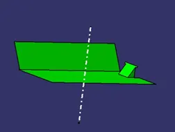
Step -5: - the next step is to add the top walls for the component for that insert the new geometrical set in the B-surface features and name as Top Walls and for extract the surface use multiple extract and select all the top faces and extrapolate the surfaces and offset the surfaces at 2.5mm outside from the Class-a surface
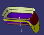
Step -6: -and create the final adding of all the features like side walls, base, and top walls create a geometrical set and name as Trims and use the trim command and trim all the unwanted surface then we can form the final surface.
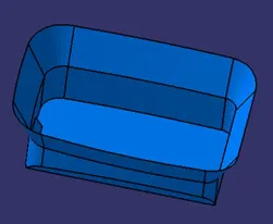
Step -7: - the remaining surface is outer flanges for the same insert the new geometrical set and name as Outer Surface and repeat the same process and use the multi extract for the surface and extrapolate the two surface and trim the unwanted surface. And off the surface.
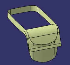
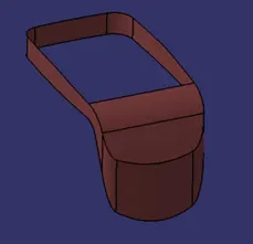
Step -8: - the next step is to create the C-surface for the add another geometrical set and name as C-surface, for this component the walls are perpendicular to the base for that the surface connecting to B-surface and A-surface is perpendicular to the B-surface and connects to the A-surface. For that we need to use the Swept command in the swept command we need to go for the second option and select the Swept with the reference surface. And select the extracted sketches from Class-A and select the surface and give a 900 angle for the swept to generate and the length of the swept is 15mm. for joining the B-surface and C-surface need to trim the unwanted surface in the C-surface then the B-surface and C-surface connected .and repeat the same process for the side hole also.
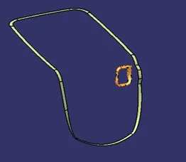
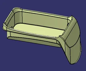
Step -9: - the next step is to connect the B&C surface to the Class-A surface. for that use the Join command and connect the 3surface into a single surface.
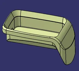
Step -10: - the final step is to create the solid part out of the surface body for that insert a part file and name as Coin Holder Part, to create the solid body use the Close surface command and select the final surface file and click on OK the final part body was created.
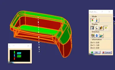
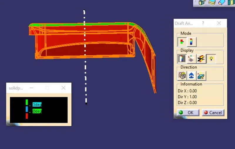
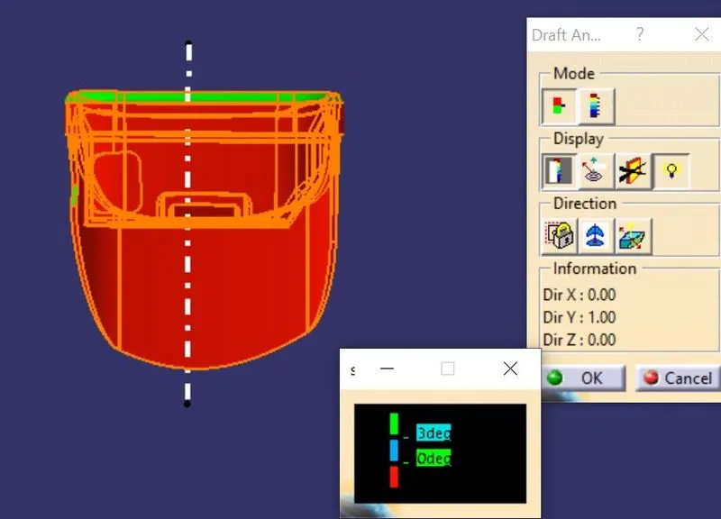
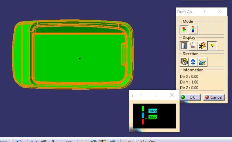
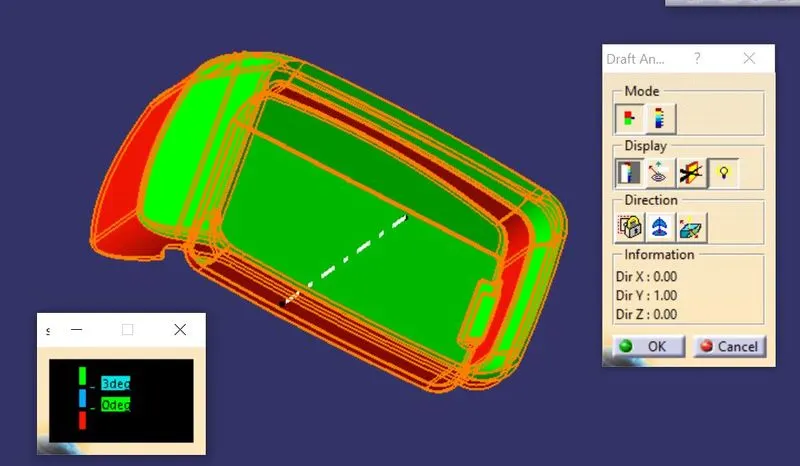
Step -12: - the next step is the Draft analysis of the component for that go to insets and Analysis to Feature draft analysis. Draft analysis interface will open and use compose option and select the UCS and fix the axis to the component. And check the draft position correct or not if it is in the wrong direction change to inverse the draft direction. Hence the final part was completed with solid features and Draft analysis.
Note: -if any changes are required for the Class-A surface don’t do the changes directly, inform the issue to the Class-A team and then do the changes I got the main issue with the sidewalls of the component it is perpendicular to the base if it is in angle position we can exact tooling direction.