Week 8 - Challenge 4 - Bumper
Design of BUMPER with the help of CATIA V5
Objective:
- To design BUMPER with respect to the class a surface.
- Create class b surface and class c surface and the tooling Axis
- Convert those class A surfaces in a close body and make it into the solid body provide the thickness of 2.5 mm
- Performing draft analysis to verify the creation of tooling axis and class C surface.
THE GIVEN CLASS A SURFACE....
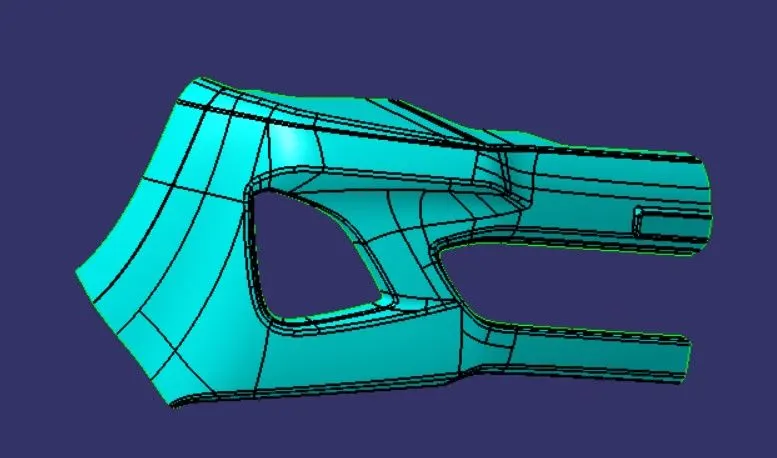
Here we are using the software catia v5 generative safe design
Design methodology with images
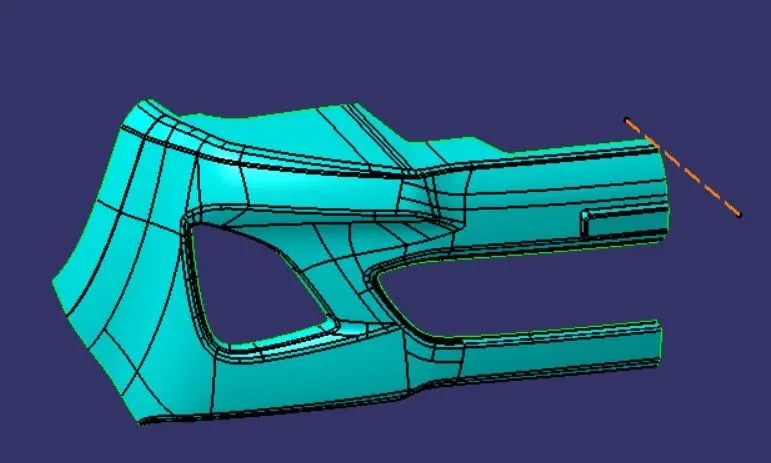
How to create tooling axis….
Create a point at the base OR any flat surface from where we can se max no. of surfaces from the class A surface.
Extend the line at that point which is perpendicular to the plane or surface
Chane the colour of that line and make it as construction geometry
Rename it as tooling axis.
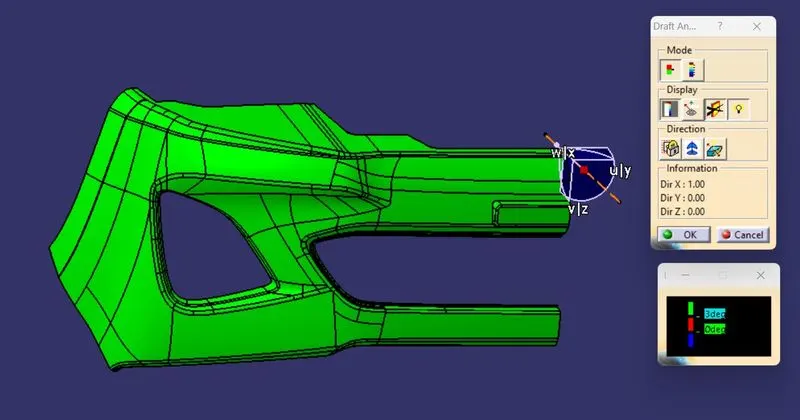
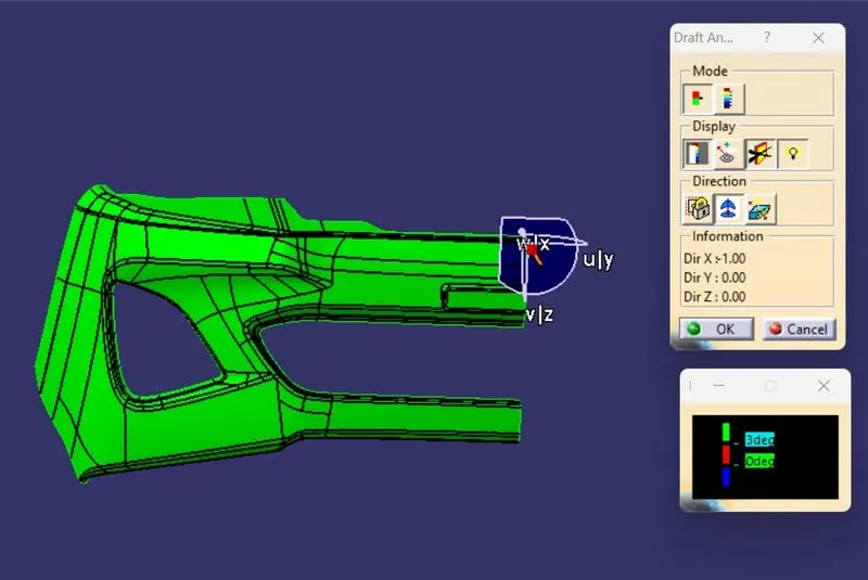
Draft Analysis for Surface A:-
The analysis is done for 3degree draft. So as can be seen all the surfaces are more than 3deg.
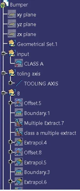
HOW TO CREAT B SURAFCE OF THE BUMPER..
Select the whole class A surface and take an offset mode by 3 mm at inside.
Now you can see some gaps are present in the offset surface….
You can fill those gaps by using multisection option, belnd option or by extracting the classA Surface.
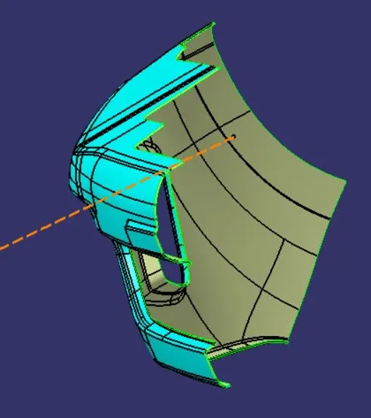
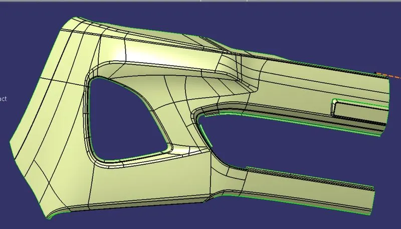
Same gaps are automatic created by taking the offset of class A surface we have fill that gaps.
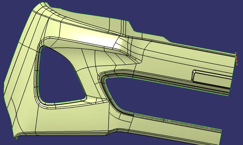
Creation of Class B:
Now for Class B creation, we have offset 3mm Class A Same gaps are automatic created by taking the offset of class A surface we have fill that gaps.
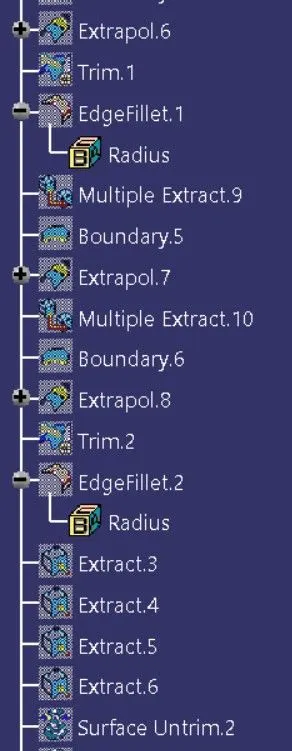
- We have filled all the gaps by using multi section.
- Required fillets are given to the surfaces.
Now we have got the class b suface
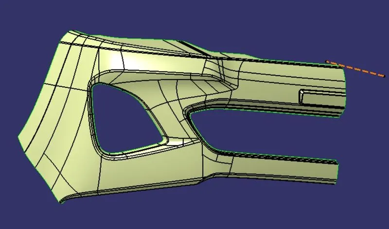
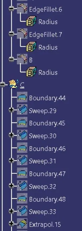
HOW TO CREATE CLASS C SURFACE…..
You can not allow to give direct sweep option by 90 degree in this case…
Because in this case there are more curved surfaces are available you can not direct extrapolate that surfaces.
So you have to take individually extrapolate that curved surfaces and flat surfaces by giving 90 degree + some draft angle
and some using of angle 0 degree.
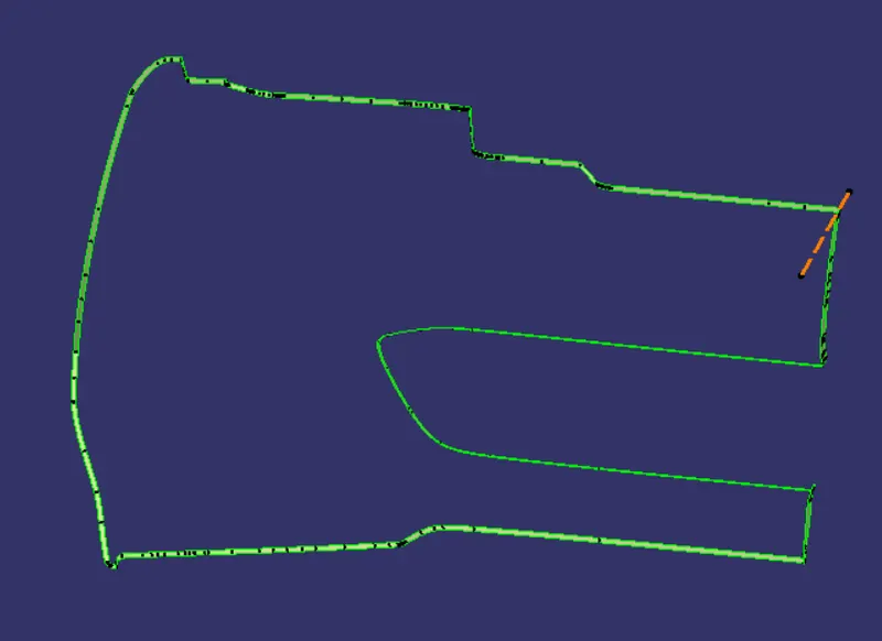
FOR FINAL MODEL
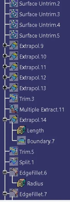
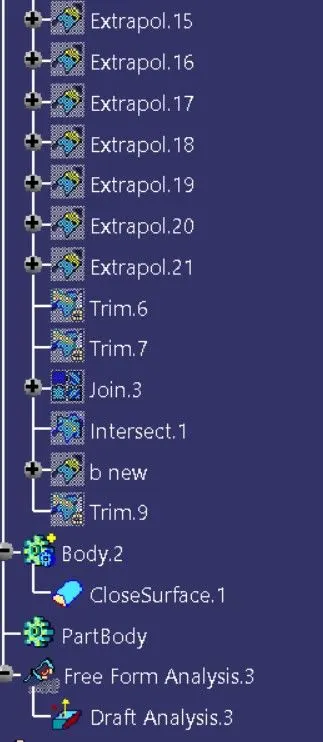
Join class-A and class-C surfaces together.
Then Trim class-B surface to them

Go to the part design and close the suface body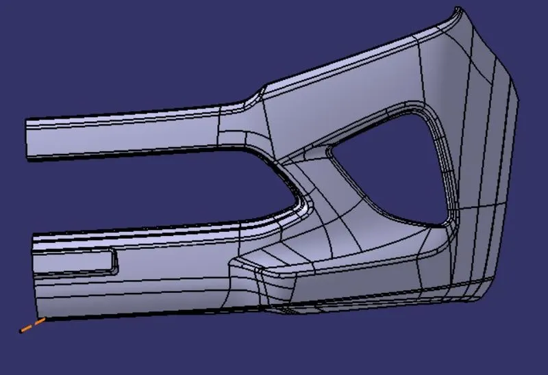
Draft Analysis on the Final Component:-
For this analysis, main tooling axis is taken draft reference.
Following results were obtained: