Wiring harness design in CATIA V5 - 3D modeling Week 2 Challenge
REPORT WRITING FOR CONNECTOR-DEUSTSCH DT06-08SA
Accroding to the given to download the CAD files in IGS FromatFrom Tyco, Electronic website as given, then to define DT06-08SA as electrical part design workbench, we need to do certain steps such as :-
First we need to do Geometry parametrs such as point & Axis to the bandel entry point. So first point parameter is given to the Bundel entry point through which the middle point-1 is generated, then point paremetr is given to the connector connection point, through which middle point-2 is generated then the AXIS parametrs is given to the connector connection point by selecting the point-2 in the origin and given X,Y,Z axises cordinate according to the locking Mechanism of connector.
Then open the Workbench select Electrical part design, then click to the command "Define Connector" in the tools section, then select the connector Geometry then a dialogue box will appear, select " Single insert connector" as a type , keep the same part number then determine the number of termination by looking to the connector and in this case as you can see DT06-08SA has 8 pole , So the termination will be 8Nos. After that you can see in the feature tree the connector is electrically defined .
Then we need to define Bundle Connection point by selecting the command in the right hand side of the toolbar then click to the connector body again , then a dialogue box will appear , let the name be as it is , in representation select the entry face of the connector , then select the (point-1) which we have created at Bundle entry point , Then initial condition will always be the same or Perpendicular to the face of the representation . Then Press OK , Now you can see in the feature tree the Bundle Entry connection point is defined and added in the properties, Then save The Data .
Now we need to Define Connector Connection Point , for that click to the connector connection point command in the right hand side of the toolbar, then a diaogue box will appear , then again let the name be same in the representation select the connector connection (point-2) which we have done earlier in the geometry parameter, then the contact will be the face of the connector Mating face, the coincidence face will be the Y-Axis & the orientation will be X-Axis ,Now you can see in the Feature tree there are 2 Things added ,one is the connector connection thing in the Electrical Properties & the second is the Reference Used for this Properties. Now Save The Data .
The next step is the Cavity Connection point but in the connector DT06-08SA as we don't have the locking Feature so this Connector is now Completely Defined and we can use it further for Wiring harness Drawing creation .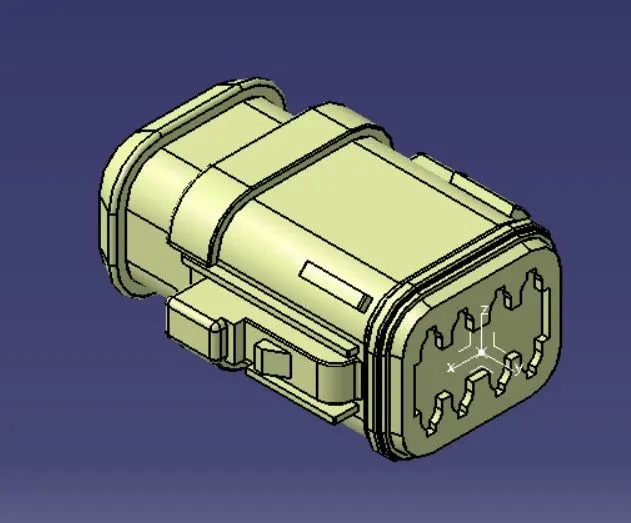
REPORT WRITING FOR CONNECTOR- TYCO 174357-2 :-
According to the given question at first we need to download the CAD files in .STP format from Tyco Electronic website as given , then to define TYCO 174357-2 as Electrical connector using Electrical Part Design workbench , we need to do certain Steps such as:-
First we need to do Geometry parameters such as POINTS & AXIS to the Bundle entry point and Connector connection point. So first, POINT Parameter is given to the Bundle entry point through which the middle point-1 is generated ,then POINT Parameter is given to the Connector Connection Point , through which Middle point-2 is generated then The AXIS parameter is given to the connector connection point by selecting the point-2 in the origin and giving X,Y,Z axises cooridinates according to the locking Mechanism of the connector . Here ,we need to give another set of Geometry parameters of POINTS & AXIS for the Cavity Connection point , where the Mounting of cavity clip in the connector clip will take place , So Point-3 is generated through the middle point feature and the AXIS is created through selecting point-3 as origin and the X,Y,Z axises will be coordinated along the Mounting of the cavity Clip . Save the Model. (NOTE- Same Orientation Should be provided in the Connector clip and the Mounting Clip ).
Then open the Workbench select Electrical part design, then click to the command "Define Connector" in the tools section, then select the connector Geometry then a dialogue box will appear, select " Single insert connector" as a type , keep the same part number then determine the number of termination by looking to the connector and in this case as you can see TYCO 174357-2 has 3 pole , So the termination will be 3 Nos. After that you can see in the feature tree the connector is electrically defined .
Then we need to define Bundle Connection point by selecting the command in the right hand side of the toolbar then click to the connector body again , then a dialogue box will appear , let the name be as it is , in representation select the entry face of the connector , then select the (point-1) which we have created at Bundle entry point , Then initial condition will always be the same or Perpendicular to the face of the representation . Then Press OK , Now you can see in the feature tree the Bundle Entry connection point is defined and added in the properties, Then save The Data .
Now we need to Define Connector Connection Point , for that click to the connector connection point command in the right hand side of the toolbar, then a diaogue box will appear , then again let the name be same in the representation select the connector connection (point-2) which we have done earlier in the geometry parameter, then the contact will be the face of the connector Mating face, the coincidence face will be the Y-Axis & the orientation will be X-Axis, now Save the Data .
The Next Step is to define Cavity Connection Point , Click to Cavity Connection Point command in the right hand side of the toolbar ,then click to the connector body a dialogue box will appear ,let the name be the same , in the representation select the point-3 which we have created , in contact select the face of the connecting clip , in Coincidence select the Y- Axis, and in the Orientation select the X -Axis. now u can see in the Feature tree the cavity connection part is added in the Electrical properties and also te references added . Save The Data .
So this Connector is now Electrically Defined and we can use it further for Wiring harness Drawing creation .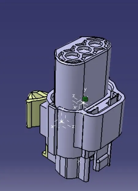
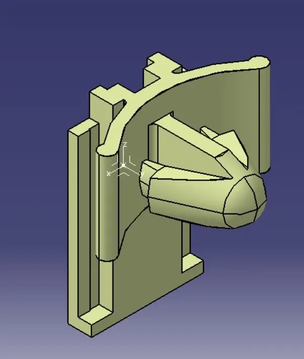
REPORT WRITING FOR CONNECTOR CLIP-TYCO 85229-1:-
According to the given question at first we need to download the CAD files in .STP format from Tyco Electronic website as given , then to define TYCO 85229-1 as Electrical connector clip using Electrical Part Design workbench , we need to do certain Steps such as:-
First we need to do Geometry Parameters Such as POINTS AND AXIS at Mounting face of the clip , So click to POINT toolbar then a dialogue box appear where the point type will be on curve ,then select middle point and Point-1 is created in the mounting face of clip. Now for AXIS parameters select the toolbar ,then in the origin select the Point-1 and set the X,Y,Z axis orientation according to the insertation of connector clip and the connector. Save the Part.
Now to define the mounting clip , go to the "Electrical Part design" Workbench , then click to the command "Define Mounting Equipment" ,click to connector click and press OK.
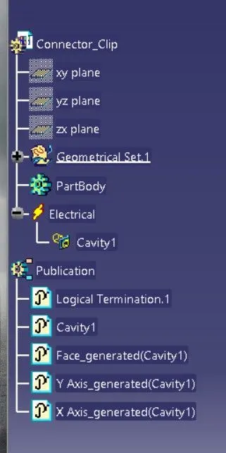
Now Click "Define Cavity" in the toolbar and press connector clip part , then a dialogue box appear , in representation select the point -1 which we have created , in contact we have to select the face that is going to mount , in coincidence we have to select the Y-AXIS and in orientation we have to select X-AXIS .Save the Data.(NOTE- Same Orientation Should be provided in the Connector clip and the Mounting Clip ).
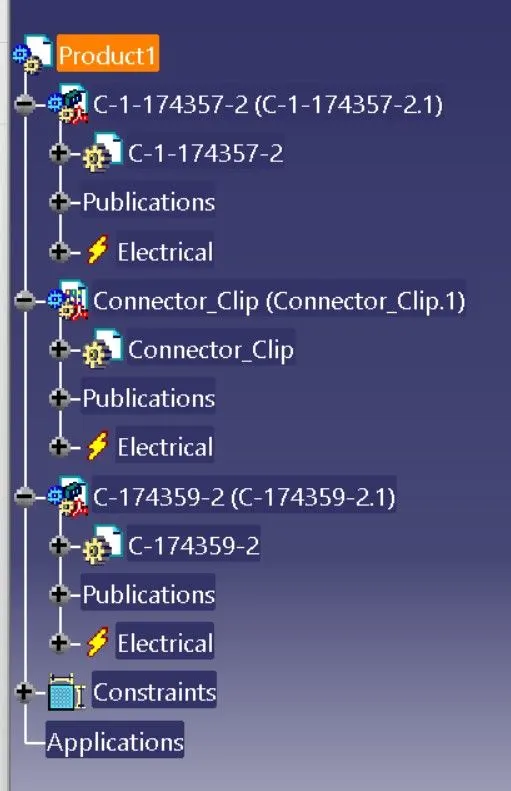
So this Connecting Clip is now Electrically Defined and we can use it for Assembly with the connector using Electrical Assembly Design Workbench .