Week 8 - Challenge 4 - Bumper
Aim :
To create Tooling axis, class B, class C surface for bumper and analysis it also published.
Objective :
Create the Bumper Plastic component through the given Class-A surface. To begin with, the tooling axis for the given Class-A Surface should be created meeting the requirements of the draft angle and at the end perform the Draft analysis on the model.
Note :
Take the Thickness of the component to be 3 mm.
Procedure To create the tooling axis, class B, class c surfaces
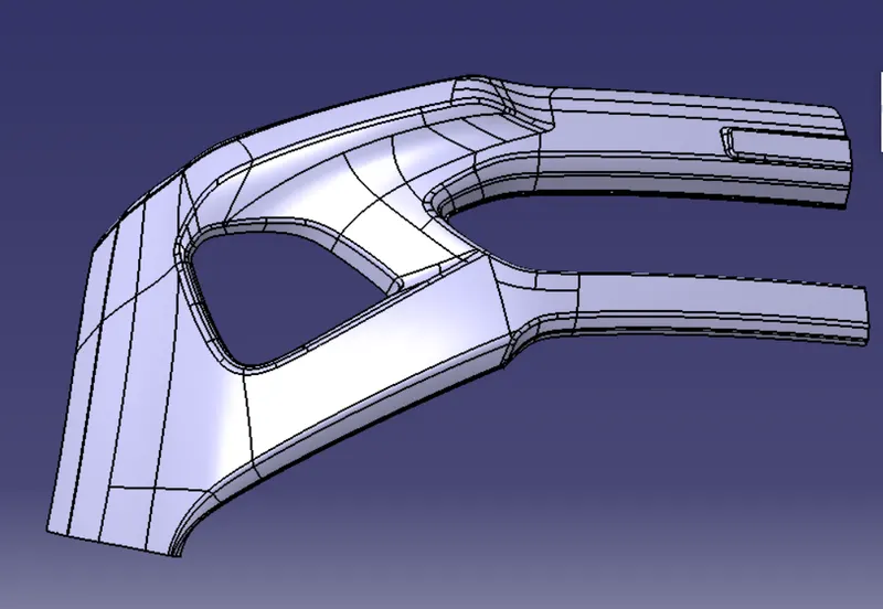
class A
in this challenge we get the catia file where is class A surface already placed we only check the no any gap and missing element on it than placed proper geometric set with proper names and select color code so easy to identify it also publish it than do furter process
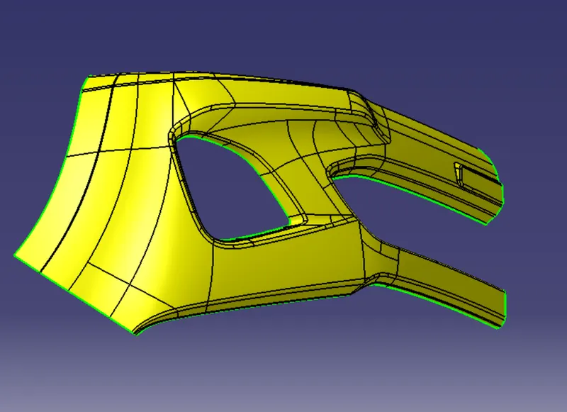
above image is class A surface than furter we create the tolling axis
Tooling axis procedure :
Tooling axis is the direction in which a core or cavity of mold opens. This Axis is very important to determine the orientation of the component in mold, core and cavity design.
here we see the class A surface in tooling axis required the oint which is used to draw the line that means tooling axis for proper directions here is diractions is is z axis only we create the pont so we get the inertia point of the bumper class A surfaces so goto the option the measure inertia
The tooling axis is created by the inertia method by using the steps as follow
1.Click on the Measure inertia than the select the A-surface
2. than click Create geometry show on the Measure Inertia window.
3. In the Creation of Geometry window, select Non-associative geometry than click Center of Gravity.
4.The Inertia point is created this point is viewed in all axes namely X,Y and Z.
used this point we create the tooling axis by line commands
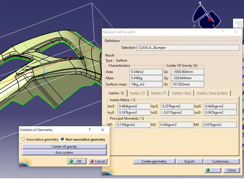
image of tooling axis with class A for two direction shown below two images
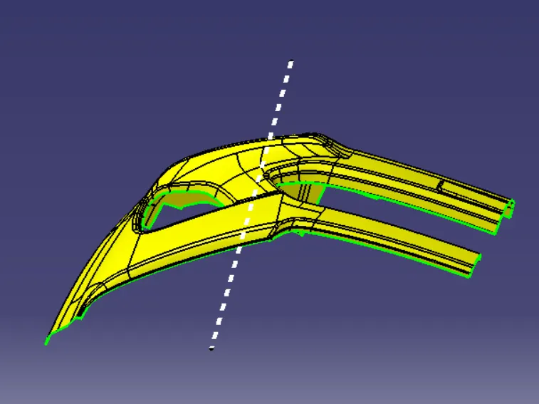
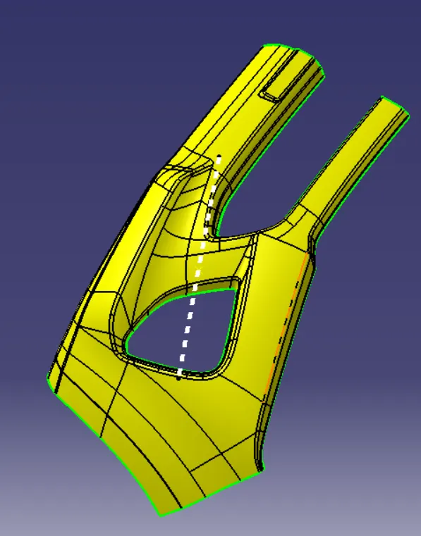
than we publish it.
B class procedure :
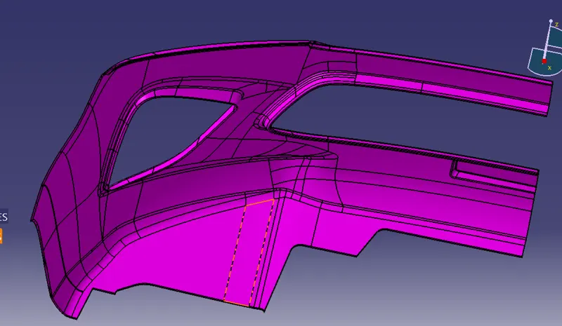
here is we create the B surface so 1st we offeset the A surface for 3 mm as per mention on the above 3mm is thickness so we offeset it for 3mm
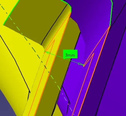
but here is some element or surface not properly offset some is missed so we can sloved it by using multiple extracs which is missed than if required to close curve so we fill it than we used the fill command and fill thus gaps and than joint it and get final B surfaces
C class procedure :
C class surface mean surface which join the class A & B surface by onther surface this called as c surfaces here is we know that Class A + Class C - Class B used this formula to create close surfaces
so we create c surface by A surface so we create boundary a surface by part by part if we take whole boundary than used sweep to create c surface that error occurces so we create boundary part by part or small surface by surface of class A surface than we used sweep command and sweep it by proper direction and angle sp we achive the close surface outcome without any error tan we use trim and join command to get our c surfaces and than we join this c surface the class A surface by according to the formulas
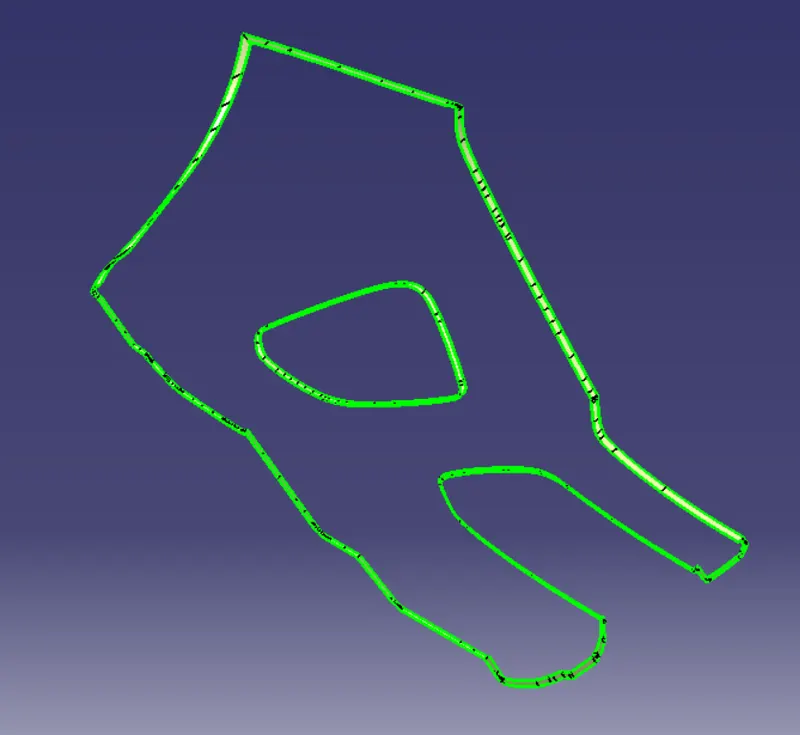
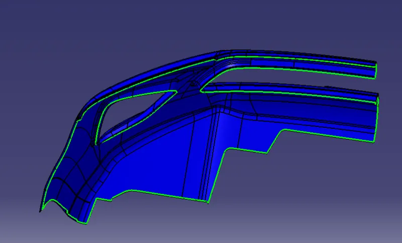
than we trim it the final c surface to the b surface get the close surface
than we solid it by colse surface command than we goto draf analysis to check draft angle right or not
Draft Analysis of Bumper body :
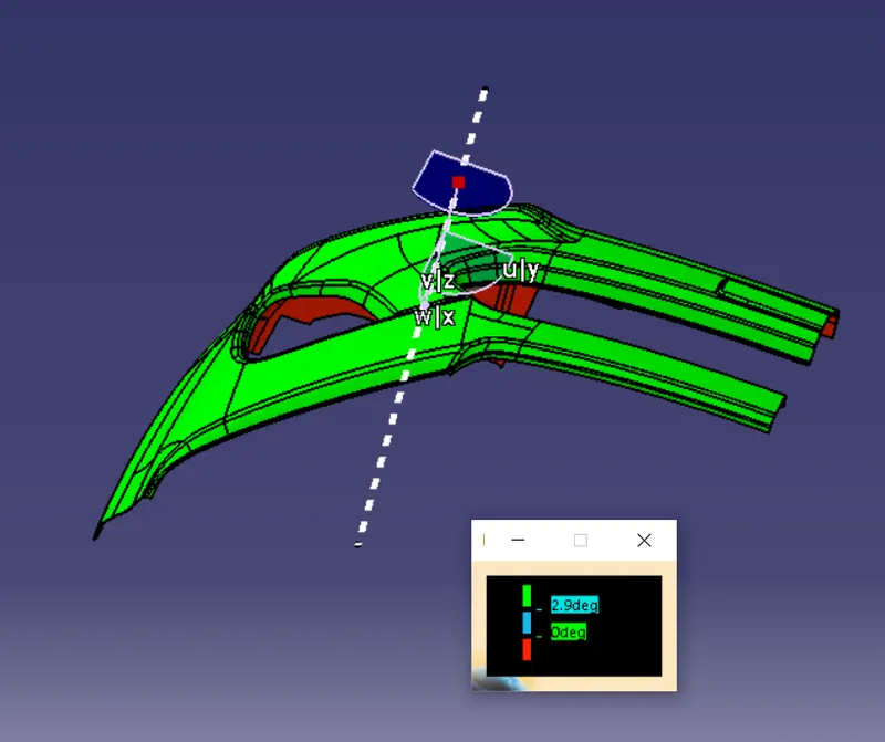
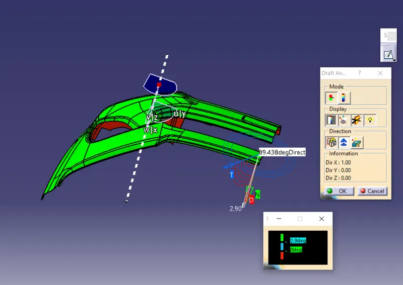
The final solid part body has to be analyzed using Draft analysis. This is done to check if all the areas of the body are satisfying the draft angle which is 2.9 degrees.
in that 1st we select draft analysis option than set the commpas diraction and arrange it properly in tooling axis with proper manner than fixed it after that we select direction of draft and analysis it if angle is greater than 2.9 dregee that surface green and 0 degree sky color and below 0 degree gives red color
A draft angle is a taper applied to the vertical walls of the injection-molded component to assist with releasing the part from the mold.
Draft angles are a required feature of injection-molded custom parts. A functional part for injection molding has to have draft angles that face both the cavity and core sides. This will reduce the risk of damage to the parts and ensure that they can be ejected from the machine.
The Bumper body is checked using Analysis and images for it are shown below.
Note : here is we attched it the catia part file for bumper this challenges pls refer it.