Week 8 - Challenge 4 - Bumper
Aim :
To A Create the BUMPER Plastic component through the given Class-A surface.
Objectives :
To begin with, the tooling axis for the given Class-A Surface should be created meeting the requirements of the draft angle and at the end perform the Draft analysis on the model.
Take the Thickness of the component to be 3 mm
- Tree Structure
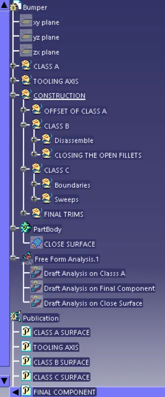
- Ensure Proper Tree Structure
- Geometrical sets should have a proper name based on the sketches present inside of it
- All the sketches should be created under the Geometrical set
- Use the Close Surface feature to make a solid body from the surface.
- Publications: Use the publication option and publish the below
- Tooling Axis
- Class A, B, and C surface
- A detailed report should be done explaining the draft analysis and the tooling axis creation.
- An explanation should be given on the way of creating the tooling axis, particularly the Bisecting method.
- Screenshots of the Draft analysis report for both the given Class-A surface and the final plastic component
- Screenshots of the solid model with the proper color code of the draft angle in various orientations (Isometric, Front, Side, and Top View)
Procedure :
- 1.First Thing is open the CATIA V5.
- 2.Open the given BUMPER CATPART file part then check if the geometrical set is properly arranged or not.
- 3.Then go to the Surface workbench
- 3.Give the proper Tooling Axis.
- 4.After that work on the BUMPER Geometrical Structure.
- 5. Ensure to check the bondaries & join them properly.
- 6.Make sure that proper dimensioning is necessary
- 7.Finally check if it is Iso Constrained (Fully Constrained) or not.
- 8. By Using Surface workbench to thicken the surface & Close them properly.
Let We Discuss in Detail Manner in Step By Step :
Class A Surface :
We Know that The Class A surfacing is the art in front of the engineering. It is the styling process brought in to digital life.
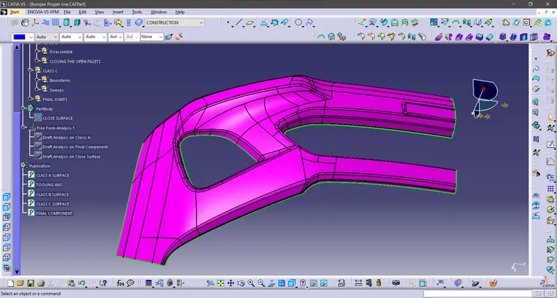
According to the given task we have to thickneed Class A Surface before that we need observe the Class A Surface carefully as shown in figure below.
Tooling Axis :
The tooling axis is a rotated an Angle 1 about the x-axis, then rotated an Angle 2 about the y-axis. Angle 1 about Z, Angle 2 about X. The tool axis is a rotated an Angle 1 about the z-axis, then rotated an Angle 2 about the x-axis.
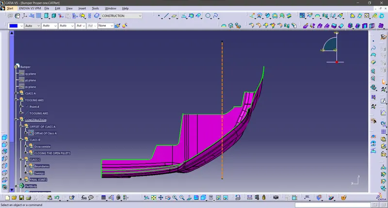
In Practical based on the removal metal from core & Cavity we need a Centre of the surface that is we called as tooling axis.
Create A Dummy lines on A Bush or hole walls & Then Intersect them.
line as shown in figure below.
Publications :
“Publishing geometrical elements is the process of making geometrical features available to different users”.
“A publication acts as a reference to a geometric or datum entity in a CATIA V5 part or product”.
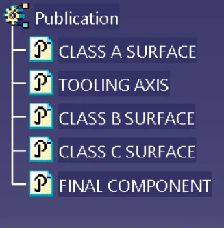
slecting the geometrical elements for easier to show or hide when we work on the catia so that we have to select the Class A,B,C Surfaces & Tooling Axis, after that go to the tools & Select the publication Click yes & Click ok, then we got the publication on the tree As shown in figure below.
So Lets Begin With The Class B Surface Creation
Insert the Geometrical set respectively,
Class B Surface :
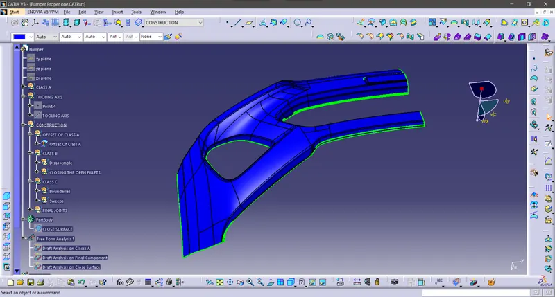
OFFSET OF CLASS A:
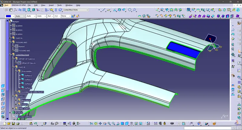
B Surface DISSEMBLING :
C By Using Class A Surface Select the dissembling split into surfaces As shown in the figure below.
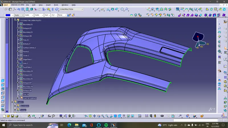
B Surface Fianl Fillets :
Give Edge Fillet to the B Surface to Measure of Class A As shown in the figure below.
Class C Surface :
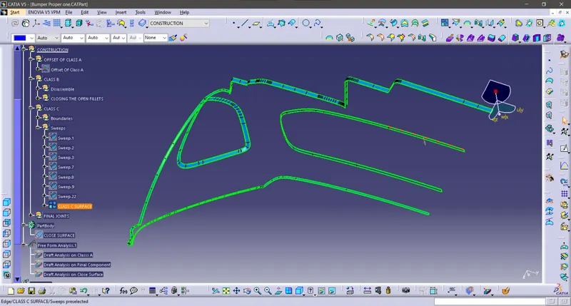
The Class C finish allows more imperfections than Class A or B. Class C is often specified for interior surfaces not readily visible, surfaces that will be covered by another part when assembled.
while constructing the C Surface We have to take the Boundaries Of Class A & Swept them & Trim & Join them then we Got the C Surface as shown in figure below.
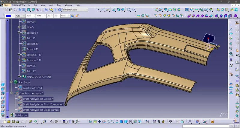
Final Joint :
Join the Class C Surface with Class A Surface & then trim it as well then we Got the Final component as shown in figure below.
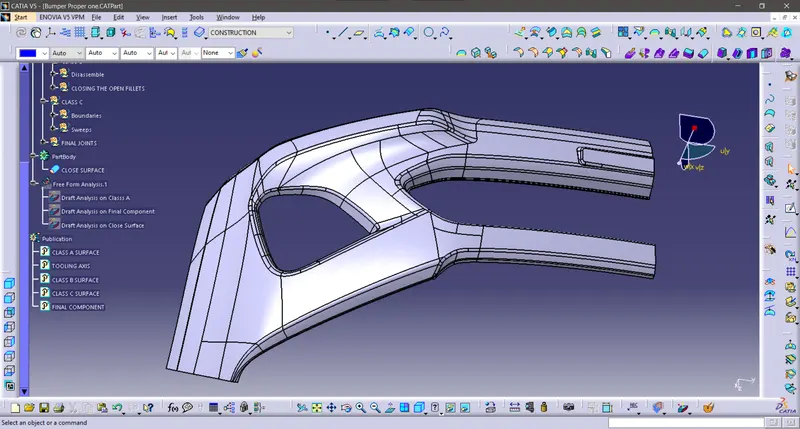
CLOSE SURFACE SOLID BODY :
A closed surface contains a volume of space, enclosed from all directions.
Go to the part design workbench & Click the close surface command & click the final trim surface component then the close surface solid body formed as shown in figure below.
Draft Analysis :
So lets discuss about the draft analysis
The Draft Analysis allows the user to easily analyze a part for proper draft angle. A Draft Angle describes the amount of taper for molded or cast parts perpendicular to the parting line.
We have 2 modes on the draft analysis Quick & Full analysis respectively.
Under the Display option we have Show are hidden the Color Scale, Analysis under the running point, No Highlight representation & Light effect.
Under the Direction option we have lock or unlock the direction, Compass & Invert.
So According to the practical Usage there Should be 1 to 3degree of angle mostly acceptable, by considering these option we have to test our given & Final Components Draft analysis.
Draft Analysis On Class A surface :
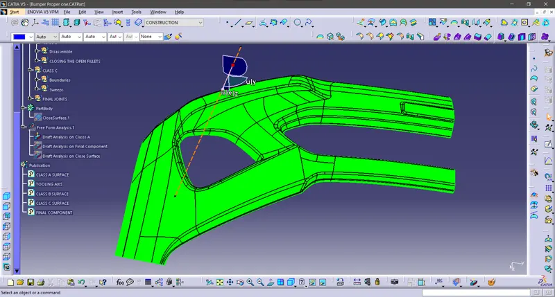
Draft Analysis On Final Component :
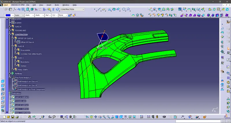
Draft Analysis On Closed Surface Solid Surface :
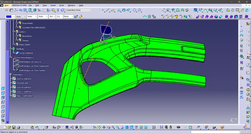
Expanded Tree Structures & Snaps as shown in given below :
Conclusion:
Successfully Created the Bumper Plastic component through the given Class-A surface.
CATpart should be submitted as an attachment in given below.