Week 8 - Challenge 4 - Bumper
Objective:
The main objective of this challenge is to create the Bumper Design Plastic component through the above-given Class-A surface, by giving the 'Tooling axis' and 'Draft analysis' to the Bumper.
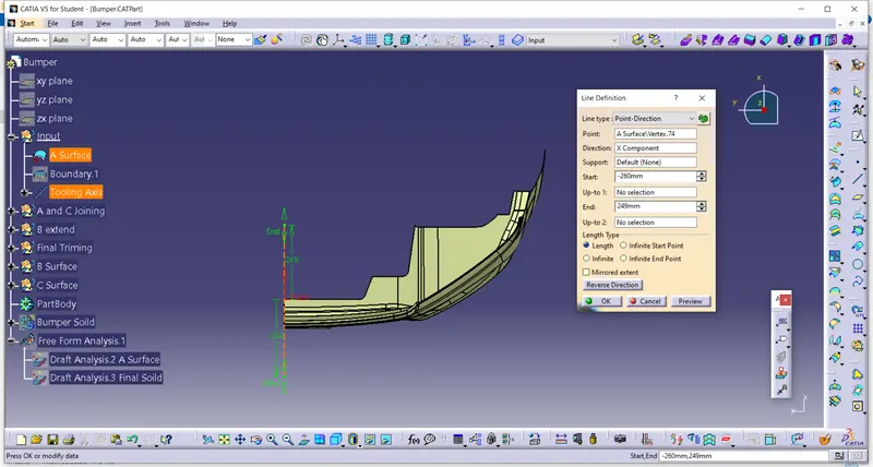
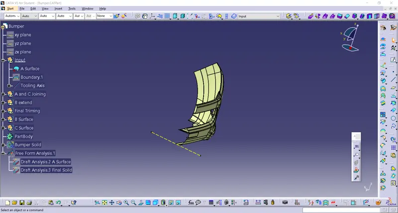
We should keenly observe and study the class A surface to create the 'Tooling Axis' for the component, for the above-given base bracket Z-axis is the best suitable tooling axis. Initially, I created a Reference tooling axis on Z-axis by considering the reference point created in the middle of the circle.
Initially Mark up in Z Direction of Reference Tooling Axis.
CLASS B SURFACE:
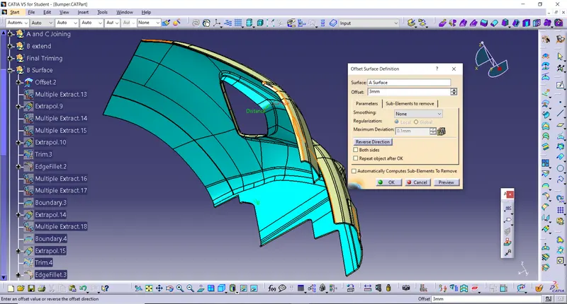
To create the class B surface, I considered the entire surface has 3 parts 'Upper, Walls, and Base surface'. If we directly offset the class A surface, fillets may lead to cause an error, to avoid the errors we need to extract the surfaces and untrim the extracted surfaces and extrapolate those untrimmed surfaces with point continuity. Now trim those extrapolated surfaces to the required shape. And finally, fillets were given to the final trim.
Given Thickness Value 3mm Offset each Following Components
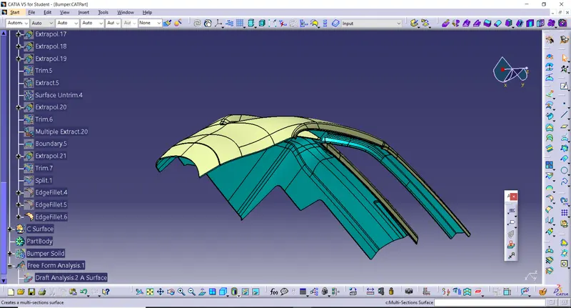
Just extrapolate 3mm on B Surface While doing step by step boundaries and then extrpolate.
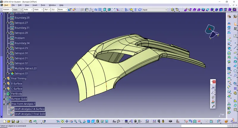
B Surface
Wheather we checked Once Created B Surface without any Patch or Gap in between them.
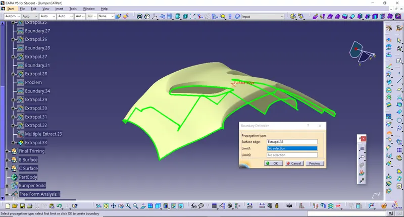
Class C Surface:
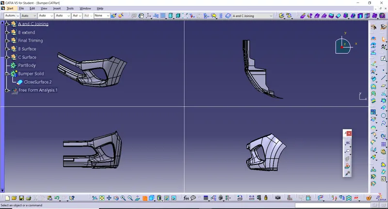
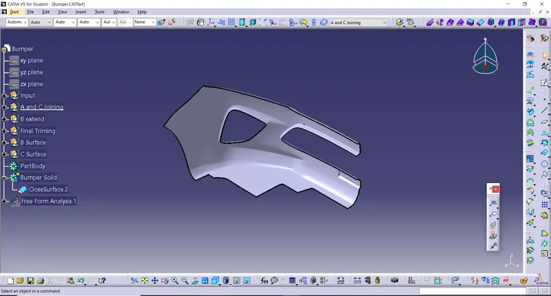
It is the combination of Class A, Class B and Class C surfaces. To create a class C surface, I used the sweep command by considering the outer boundary of the class A surface. In the sweep command, go to the 'line' command in the 'profile' block and the subtype is 'with draft direction'. Now select the outer boundary and tooling axis, give 3 deg in the angle (the draft angle for a plastic component is 0.5 to 3 deg) and select the direction to sweep, in this condition the class B surface is under the class A surface so select the inside down arrow to sweep. The same procedure is repeated for the two circles on the class A surface. Now I joined all the sweeped surfaces by using the 'join' command and then I trimmed the Class A, Class B and Class C surfaces to make a closed surface, to make a Solid body.
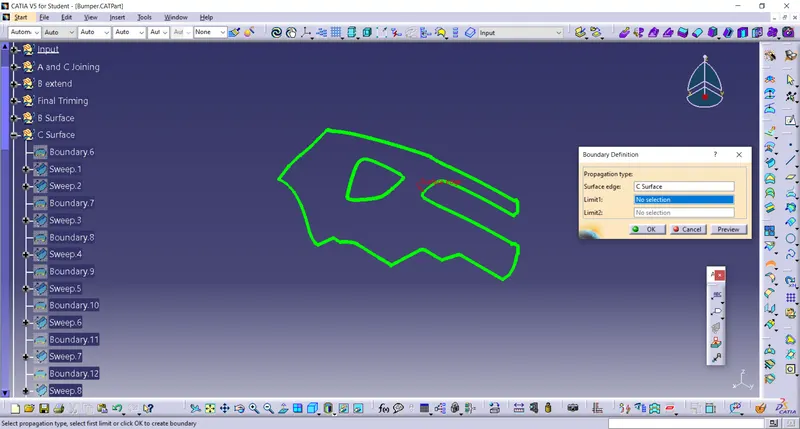
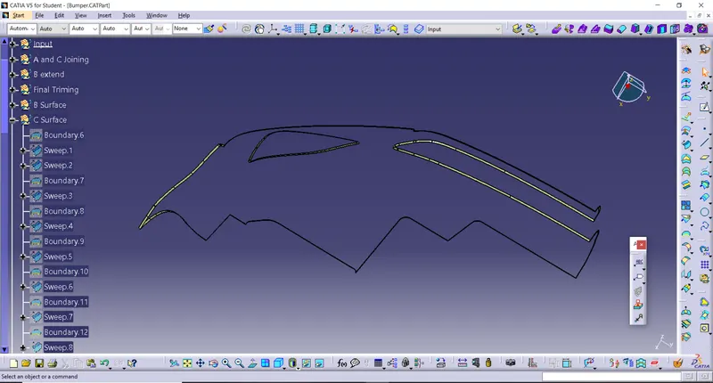
Joining A and C Surface
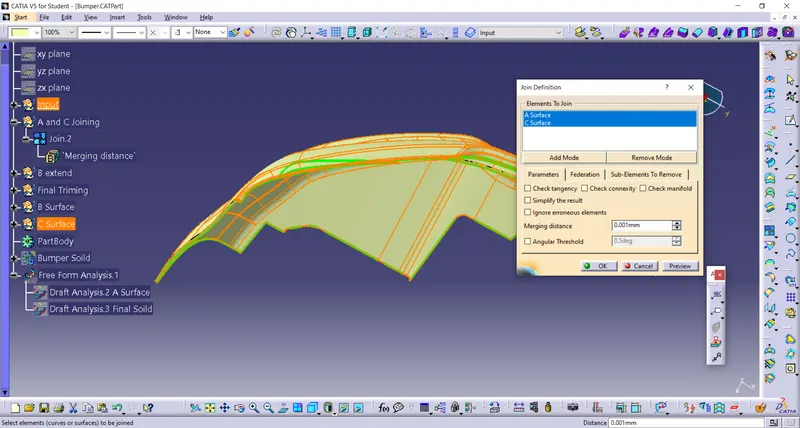
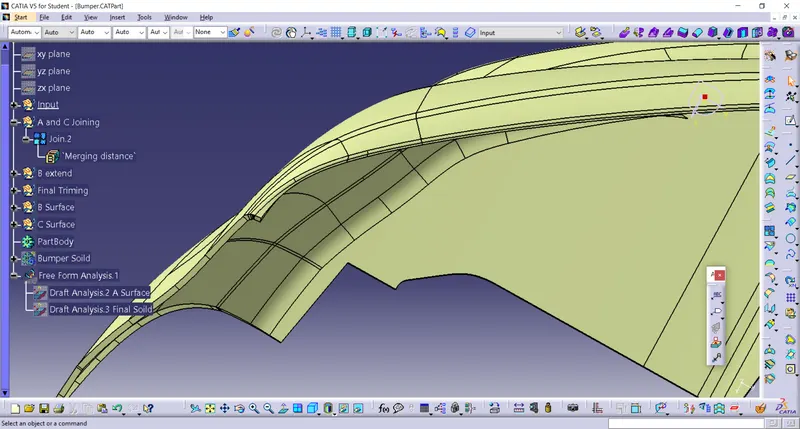
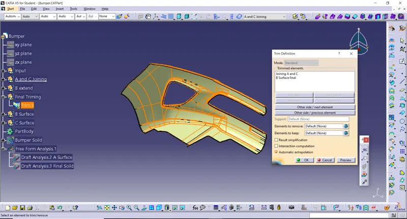
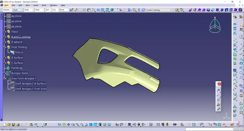
Tree Features 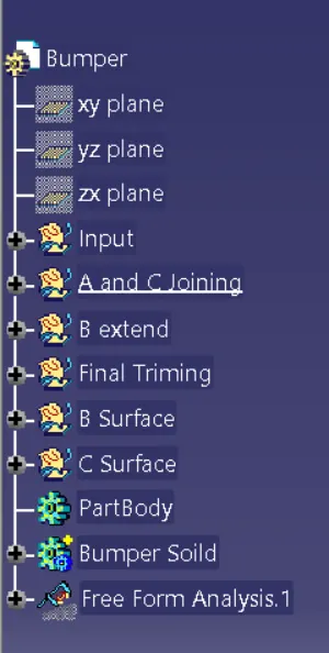
Draft Analysis
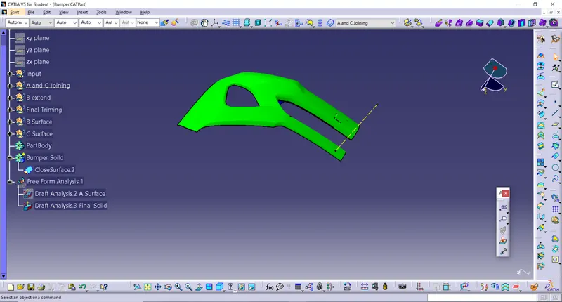
The draft analysis technique is used to analyze whether our part model created in CAD is manufacturable based on the draft condition applied. Here the part should get easily removed from the panel dies (in case of Sheet metal part) or Mold (in case of plastic).
No parts can be ejected from the tool if it is having a straight 90-degree profile from its base surface. A small draft angle is provided to each and every area of the component in order to get easy removal of the component from the tool.
Here we are providing a direction in which components should eject in order to get easy removal of components from the tool. In other words, it also lets us know whether the model is having a draft angle and how much is the draft angle from the tool direction.
Conclusion
Here, Sucessfully to create the Bumper Plastic component through the above-given Class-A surface, by giving the 'Tooling axis' and 'Draft analysis' to the Coin Holder.