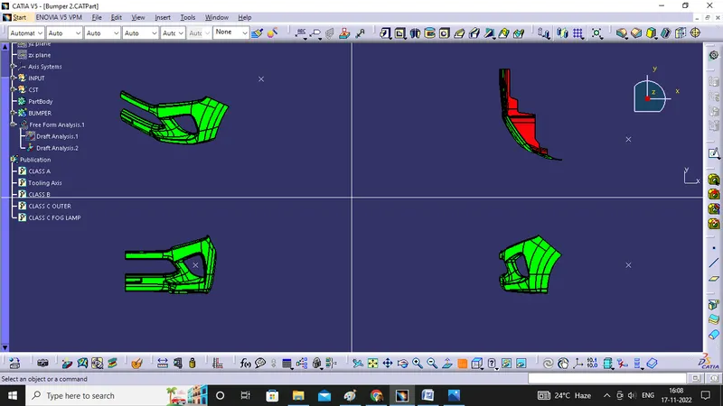
Week 8 - Challenge 4 - Bumper
Aim :-
- Creation of BUMPER plastic component through the given Class-A Surface using CATIA.
- Detailed explanation of Draft Analysis and Tooling Axis creation.
- Explanation of Bisecting method of Tooling Axis creation.
Theory :-
- Before designing any component through its given Class-A,first we need to do some DESIGN RULES CHECKS i.e.,ensuring that the given Class-A doesn’t have any gaps between its surfaces.
- TOOLING AXIS :- 2nd Step is the Creation of Tooling Axis (It is the direction along which the mold moves).
- To decide the Tooling Axis for a given Class-A,we need to ensure that the component is clearing the Tooling in that particular direction.
- We must try to include any HOLES or SLOTS in the main tooling itself which will lower the cost of component by avoiding the SIDE CORE.
Creation TOOLING AXIS by BISECTION METHOD :-
- Faces of the component are identified first which may create a problem at the time molding.
- In this method,Sketches are being made along with their Intersects to check whether the component’s faces are clearing the Tooling Axis in a particular direction.
- Sketch which we obtained after intersecting the faces with the respective planes,lines that are parallel or have small inclinations with the expected Tooling Axis (made for reference purpose) are only checked by creation of construction lines along them and bisecting them at last.
- Bisection method is only applied in the direction where we have a doubt that the particular face is not going to clear the tooling.
- The faces that are perpendicular or near to 90 degree with the Tooling Axis clears the tooling easily and we don’t need to apply Bisection on their sketches.
- Bisected lines if more than one, are again bisected to get the Tooling Axis before doing Draft Analysis of the CLASS-A.
Draft Analysis :-
- Draft Analysis is done to ensure that the solid component or its given Class-A skin meets the prescribed Drafting standards.
- In Automotive Industries,3 degrees draft is usually accepted as a norm amongst the Product Designers and the Mold Makers.
- Before performing the Draft Analysis,Tooling Axis is made in a manner that the component along with its Holes,if any,clears the selected tooling direction.
- Now,the 1st step is to define the Current Draft direction by dragging and merging the compass on the top right corner of the CATIA window with our Tooling Axis and then locking the draft direction.
- Picking the surface by clicking on it shows the different drafts given on the various parts of a component with the help of colors whose values can be estimated from the Color Scale in the Display option.
- Make sure to give a minimum of 3 degrees draft on the color scale.
- We can manually check draft on all the faces by choosing the ‘Analyses under the running point’ in the Display option of the Draft Analysis Toolbox and then we can move on to the creation Class-B surface.
Draft Analysis on Bumper :-
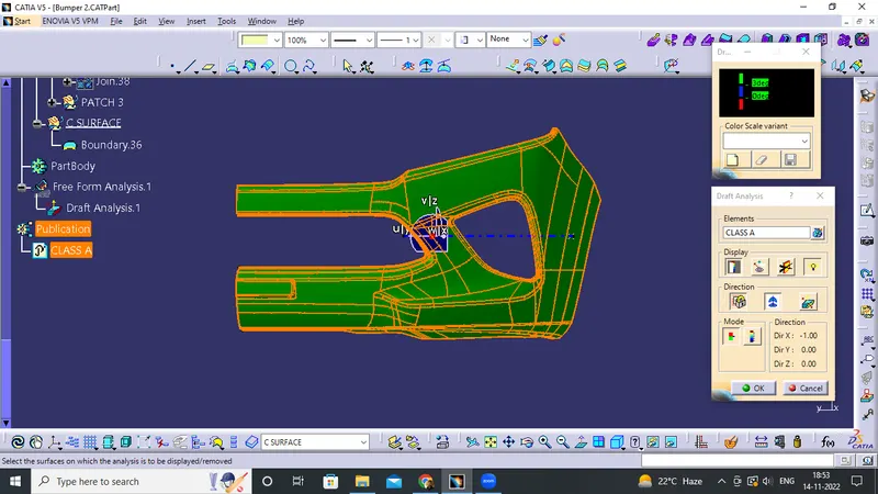
Analyzing Class-A :-
- Upon performing the draft analysis,we saw that all the surfaces are above the specified 3 degrees draft.
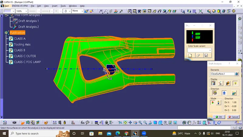
Analyzing Solid Model (Bumper) ;-
- Upon performing Draft Analysis on the Solid,we saw that all its surfaces are clearing the minimum requirement of 3 degrees draft.
Screenshots of the Solid Model :-