Analysis of Otto Cycle
AIM : To write a program in MATLAB -
- That solves an Otto Cycle and make P-V plots.
- Calculates it's Thermal Efficiency.
THEORY :
Working of 4 stroke SI Engine :
Air Standard Assumptions : While applying the below relations at different states the following assumptions are taken into consideration.
- Air is the only Working fluid .
- Air is assumed to be a Perfect Gas i.e., Ideal Gas Equation is valid (PV = mRT) & Cp,Cv & gamma is taken as constant (for real gases they are function of temperature).
- Heat Addition :- Although my Chemical Energy (of Air-Fuel Mixture) is transforming into Thermal Energy inside my system ,but,Nicolaus Otto assumed that my heat is being added externally in order to conform with the thermodynamics.
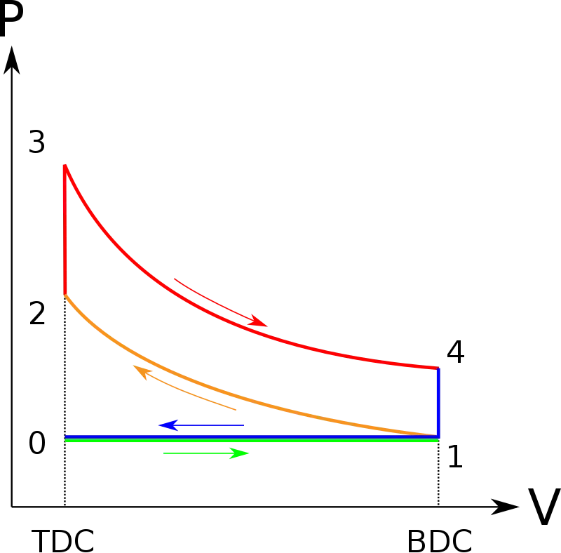
- Suction Stroke : (Process 0-1)
- Firstly an Air-Fuel Mixture (AFM) @ Atmospheric Pressure get's drawn into the cylinder from the inlet valve due to creation of partial vacuum (Pressure inside the cylinder (P_cyl) < Atmospheric Pressure (P_atm)) because of the movement of piston from the TDC (Top Dead Centre) to the BDC (Bottom Dead Centre) till the P_cyl becomes equal to P_atm.And,the inlet valve get's closed the moment piston reaches BDC.
2.Compression Stroke : (Process 1-2) (Isentropic Compression , P*V^gamma = constant & PV = mRT ) :
- Now,this AFM is compressed till TDC until the P_cyl > P_atm (P_cyl ~ 10 bar) and the respective temperatures T_cyl & T_atm becomes T_cyl > T_atm .
- Also,the temperature inside the cylinder (T_cyl) >= Flash point temperature (T_flash).
- And,the governing equations are:
- (T2/T1) = (P2/P1)^(gamma-1/gamma) = (V1/V2)^(gamma-1)
3.Constant Volume Heat Addition : (Process 2-3)
- Now,using an external source (i.e.,Spark Plug) heat is added to this compressed AFM.
- Spark Plug :
- For sparking very high voltage (V=10,000 Volts +-) is required to overcome the air resistance present between in the spark gap.
- Spark plug should be ideally made up of Platnium(due to high electron density) but practically,it should be made up of Nickel alloys as it is having coefficient of thermal expansion (k) tending to zero i.e.,high thermal resistance.
- Temperature of Spark (T_sp) ~ 1600 deg +- .
- Platnium is not used because it's expensive and thermally insensitive.
- Current (I) is low as 1 mA due to battery limitations.
4.Expansion/Power Stroke : (Process 3-4) (Isentropic Expansion , P*V^gamma = constant & PV = mRT) :
- Now,due to the above heat addition process the pressure inside the cylinder becomes approximately equals to 50-60 Bar which causes the movement of the piston to BDC
- The equation governing the above process is :
- (T3/T4) = (V4/V3)^(gamma-1) = (P3/P4)^(gamma-1/gamma).
5.Constant Volume Heat Rejection : (Process 4-1)
- At BDC, after the power stroke, major exhaust (~ 90 %) gases from the cylinder escapes out by opening of the exhaust valve.
6.Exhaust Stroke : (Process 1-0)
- The minor or remaining exhaust gases are swept out by the movement of the piston from BDC to TDC and the above processes keeps on repeating as long as the engine is in running condition.
P-V Graph :
The below graph shows the various processes as explained above
Formulae used :
- V_s = pi/4 * bore^2 * stroke where V_s - Swept Volume .
- V_c = V_s / (r-1) where V_c - Clearence Volume , r - compression ratio
- The change in volume wrt crank angle (theta) is given by :

where V - Volume corresponding to the position of the crank.
V_c - Clearence Volume
r_c / r - compression ratio
R - Obliquity ratio = stroke / a
a - crank pin radius
- Here,I've used r_c & r interchangeably.
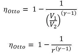
Thermal Efficiency of this Air Standard Cycle is calculated using the below equation :
Methodology :
- Alloting the input values of the Engine Geometric parameters.
- The state variables i.e.,Pressure,Volume & Temperature at state 1 are given.While the value of v1 is calculated using the engine parameters.
- The value of gamma (i.e., 1.4 for air) & temperature at state 3 are also given (i.e., either t3 or p3 must be given).
- Swept (v_s) and clearence (v_c) volumes inside the cylinder are calculated using the appropriate formulas as shown in the code.
- The state variables at state 2,3 & 4 are calculated using the below thermodynamic relations as shown in the code.
- For generating the isentropic compression & the expansion curve,a relation is given above showing variation of the cylinder volume with the crank angle is been defined as Engine_Kinematics in different program and called in current for generating the required curves.
- Once all the state points are plotted,Thermal Efficiency of the cycle is calculated.
- Ultimately,a P-V plot is created using plot command.
MATLAB CODE :
clear all
close all
clc

% Inputs (given)

gamma = 1.4 ; % (for Air )
t3 = 2300 ; % (Either p3 or t3 must be given & they are maximum at the end of compression process i.e.,state 3)

% State 1 (Pressure (Pa),Temperature (K) )

p1 = 101325 ;
t1 = 300 ;

% Engine geometric parameters

bore = 0.1;
stroke = 0.1;
con_rod = 0.15; %(Connecting Rod Length)
r = 12; % compression ratio

% Calculating the swept volume and clearence volume
% Swept volume (v_swept) is the volume swept by the piston from TDC to BDC
% Clearence Volume (v_clearence) is the volume left out in the cylinder for valves and
% spark plug installation
v_swept = pi/4 * bore^2 * stroke;
v_clearence = v_swept/(r-1);

v1 = v_swept + v_clearence; %(At state 1,BDC,the volume of the cylinder is represented by it's entire volume )
v2 = v_clearence;

% State 2 (Compression Stroke)

% p1v1^gamma = p2v2^gamma (For Adiabatic process this equation is valid)
% p2 =p1*(v1/v2)^gamma = p1*(r)^gamma;

p2 = p1*r^gamma;

% p1v1/t1 = p2v2/t2 ; t2 = p2v2t1/p1v1;(Since,air is assumed as a perfect
% gas,therefore,Ideal Gas Equation is valid i.e., PV/T = constant

t2 = p2*v2*t1/(p1*v1);

% Code for generating Isentropic Compression curve
constant_c = p1*v1^gamma;
V_compression = Engine_Kinematics(bore,stroke,con_rod,r,180,0) % (Function call)
P_compression = constant_c./V_compression.^gamma;

% State 3 (Expansion/Power stroke)

v3 = v2 ;


% p3v3/t3 = p2v2/t2 ; p3 = p2*t3/t2;

p3 = p2*t3/t2;

% Code for generating Isentropic Expansion Curve
constant_c = p3*v3^gamma ;
V_expansion = Engine_Kinematics(bore,stroke,con_rod,r,0,180)
P_expansion = constant_c./V_expansion.^gamma;


% State 4
 v4 = v1;

% p3v3^gamma = p4v4^gamma ; p4 = p3*(v3/v4)^gamma
p4 = p3*(v3/v4)^gamma

% Thermal Efficiency
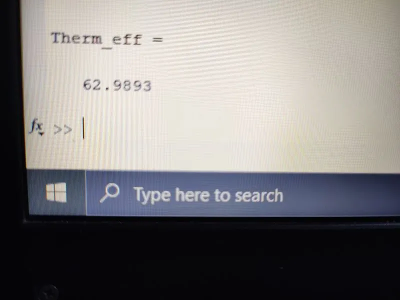
Therm_eff = (1-(1/r^(gamma-1))) * 100


figure(1)
hold on

plot (v1,p1,'*','color','r')
plot(V_compression,P_compression)
plot(v2,p2,'*','color','r')
plot([v2 v3],[p2 p3],'color','b')
plot (v3,p3,'*','color','r')
plot(V_expansion,P_expansion)
plot(v4,p4,'*','color','r')
plot([v4 v1],[p4 p1],'color','b')
xlabel('Volume (m^3)')
ylabel('Pressure (Pa)')
Function definition code :
% Defining the function Engine_Kinematics for the program above program i.e., Otto_Cycle_1

function = Engine_Kinematics(bore,stroke,con_rod,r,start_crank,end_crank)

% Program showing how volume inside the combustion chamber varies with crank
% angle and also showing isentropic compression and expansion curve on P-V plot

a = stroke/2  % (crank pin radius) (Assuming it as a Square Ratio Engine i.e.,stroke = Bore (2*a) )
R = con_rod/a % (obliquity ratio)

v_s = pi/4*bore^2*stroke;
v_c = v_s/(r-1);

theta = linspace(0,180,180);

term1 = 0.5*(r-1);
term2 = R + 1 - cosd(theta);
term3 = (R^2 - sind(theta).^2).^0.5;

V = (1 + term1*(term2-term3)).*v_c;


end
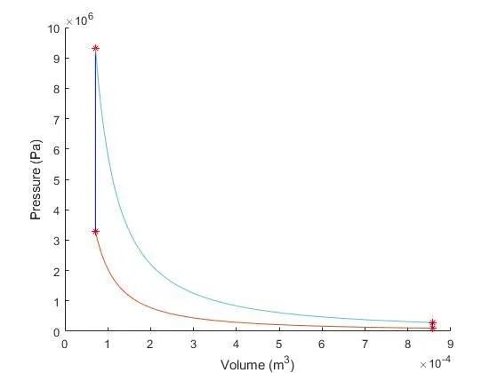
Output P-V plot : In the below plot -
- Red curve & light blue curve represents Isentropic (Reversible Adiabatic) Process represented mathematically by P * V ^ gamma = constant.
- While,dark blue lines represents Constant volume heat addition & rejection processes respectively.
Thermal Efficiency :-
Errors occured while obtaining the required output :
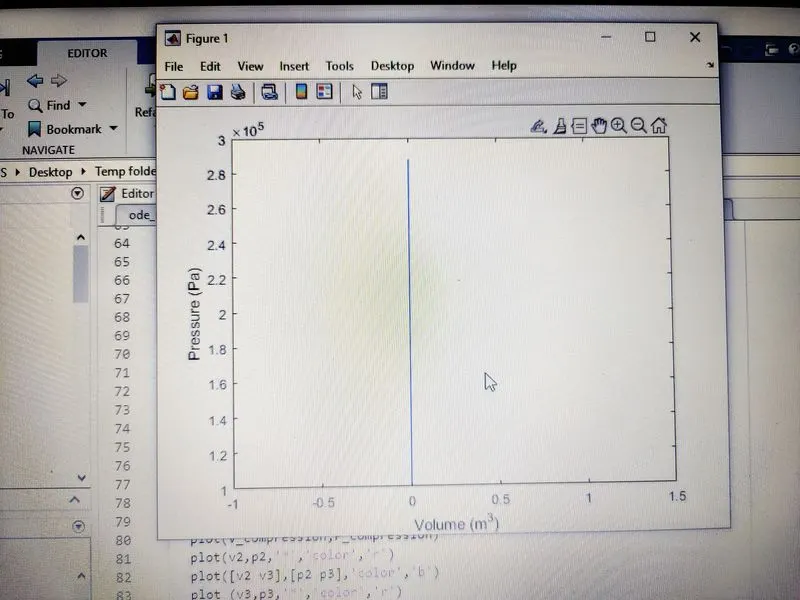
- While obtaining the required P-V plot,if hold on command isn't used before the plot command,the following figure we'll get
Solution :
- Using 'hold on' command,we can eliminate the above problem.