Week 8 - Challenge 4 - Bumper
Aim: To create the Bumper plasic Component using given Class A surface.
Consider taking thickness of the component to be 3mm.
Class A Surface: Surface made by the designer which si given as the input to work on. It is an aesthetic surface
Class B Surface: Surface below the Class A surface at certain thickness and on which engineering aspects are provided.
Class C Surface: Surface which joins Class A and Class B surfaces.
Tooling Axis: It is defined as the axis in which the mould or core and cavity opens and closes.
Introduction about Bumper
A bumper is a structure attached to or integrated with the front and rear ends of a motor vehicle, to absorb impact in a minor collision, ideally minimizing repair costs.Bumpers of most modern automobiles have been made of a combination of polycarbonate (PC) and acrylonitrile butadiene styrene (ABS) called PC/ABS.
Design Methodology
From the given Class A surface,the first step is to check the continuity of the class A surface. This is to ensure that there is no gap between surfaces. If we find any then we should fix that first. To make sure that the given surface has no gap in between them. We can check it also with the help of Join or boundary commands.
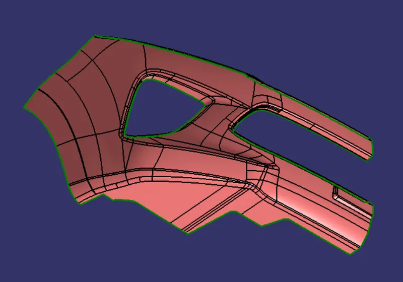
Figure: Class A surface
Tooling Axis:
- Check the best tooling direction for the given surface by cross checking all the three axes.
- We find the best tooling direction for the given Class A surface is in X-Direction.
- Then extract the surface and create a midpoint on the surface and sketch a line normal to the surface passind through the point.
- Hence, the line created is named as the " Tooling Axis".
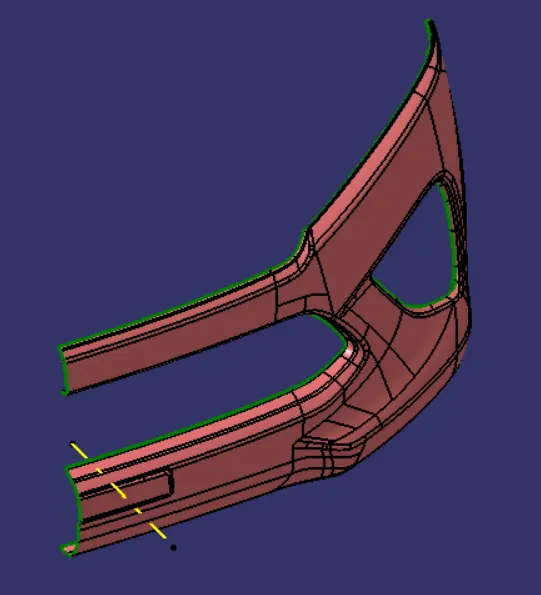
Figure: Class A surface along with Tooling Axis
Draft Ananlysis on Class A surface
- The Draft Analysis is a command enables you to detect if the part you drafted will be easily removed.
- It is performed after creating the tooling axis, draft analysis is performed for checking whether the minimum draft is provided or not.
- We change the view mode of the component to be in customized parameter mode and then select the shading mode as materials.
- Then lock the compass on the tooling axis and perform the draft analysis. We check the draft analysis on the individual faces. It shows how much draft on specific points when we move the cursor point.
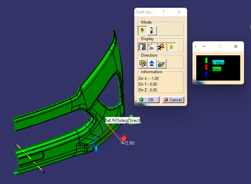
Figure: Draft Analysis on Class A Surface
Class B Surface
- Offset the Class A surface to 3mm inward direction
- Then we rework on the patches of the offset surface by using the opreations such as Extraxt, Multiple extract, Extrapolate, spline, Join, Multisecton surface, edge fillet etc.,
- To check the connectivity of the Class B surface apply the boundary command on the created Class B surface to findout the boundary.
- If any internal boundary is not found hence the Class B surface creation is done.
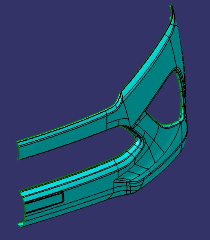
Figure: Class B surface
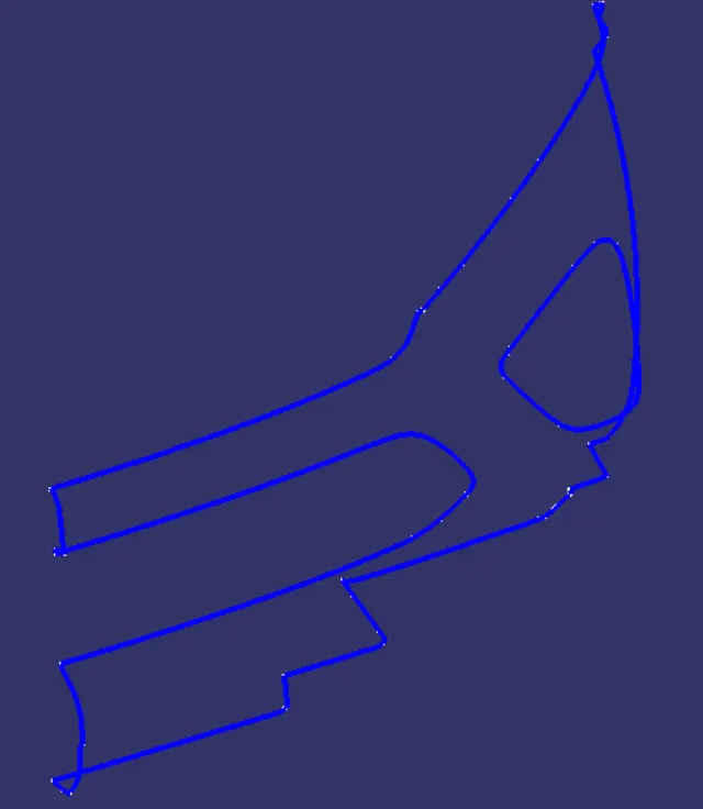
Figure: Class B surface boundary
Class C Surface
- Class C surface joins the Class A Surface and Class B surface.
- As the given Class A surface is complicated, we perform the sweep operation of 90 degrees with reference to the surface option by creating smaller boundary.
- Error formed on the edges on the sweep are recorrected by making smaller boundary and performing sweep on them.
- Finally, we join the class A and Class C surfaces.
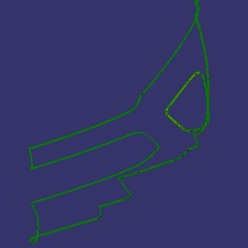
Figure: Class C Surface
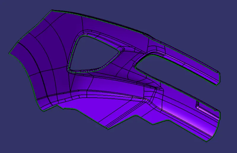
Figure: Class A+C Surface
Final Closed Surface
- Some error may rise while trimming as some edges of the class B surface may not intersect wit hthe joined surface.
- We extrapolated those edges and apply the trim operation to finally get the closed surface
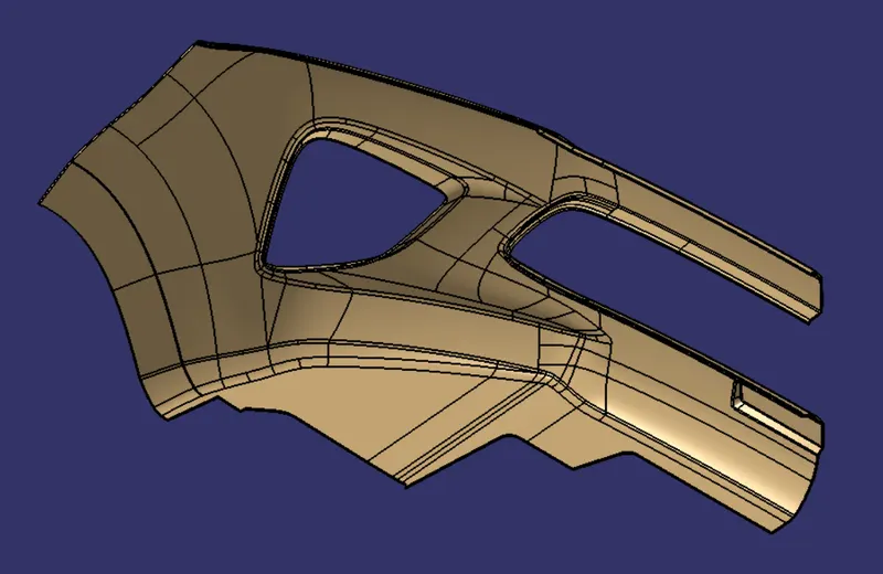
Figure: Final Closed Surface
- Then apply the closed surface command on the final closed surface in the Part workbench
- Next apply the draft analysis on the Closed Part body by changing the view mode to material shading.
- Align the compass on the Tooling axis and lock it and perform the draft analysis.
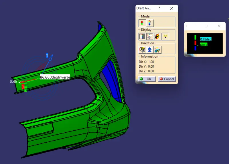
Figure: Draft Analysis on the Final Closed Part body (Bumper)
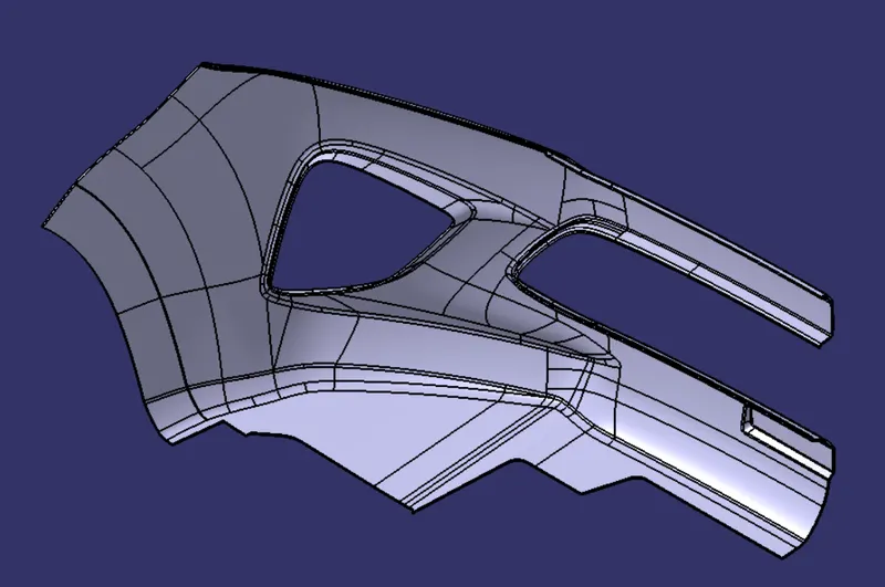
Figure: Isometric view of Closed Partbody
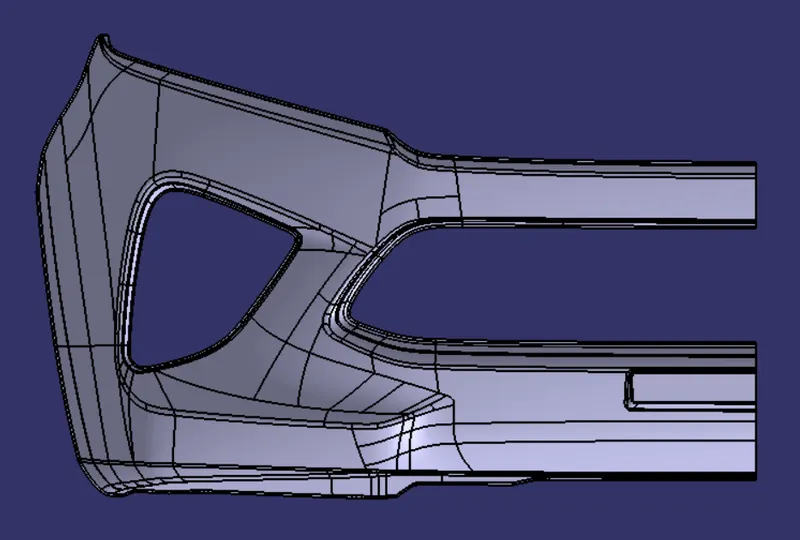
Figure: Front view of Closed Partbody
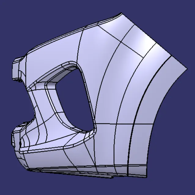
Figure: Side View of closed Partbody
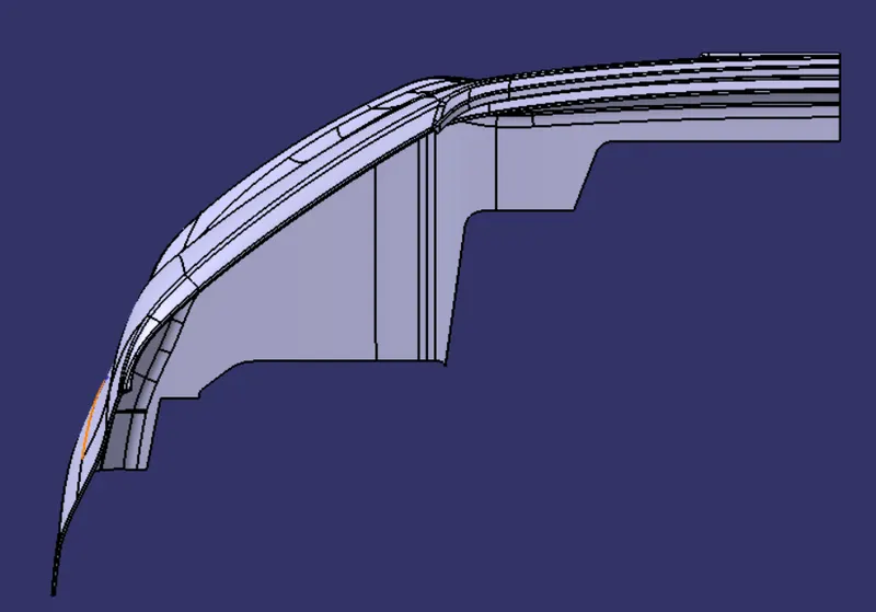
Figure: Top View of closed partbody
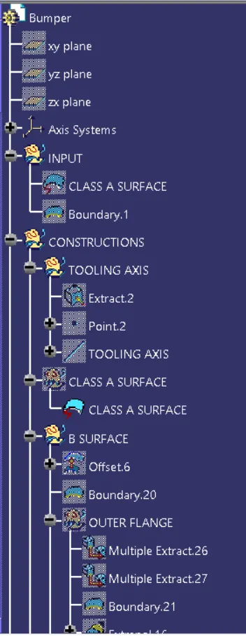
Figure: Expanded Tree(1)
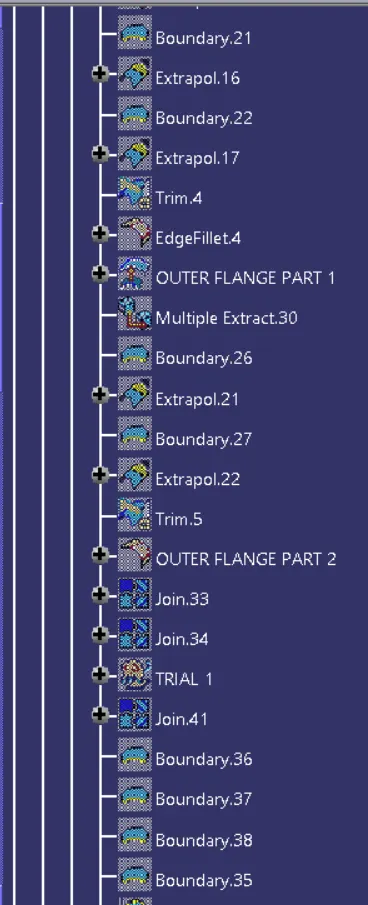
Figure: Expanded Tree(2)
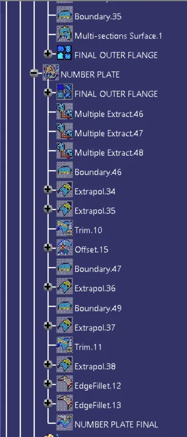
Figure: Expanded Tree(3)
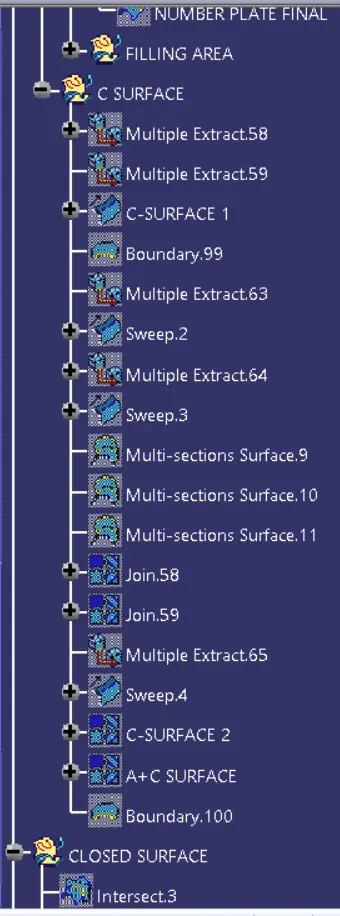
Figure: Expanded Tree(4)
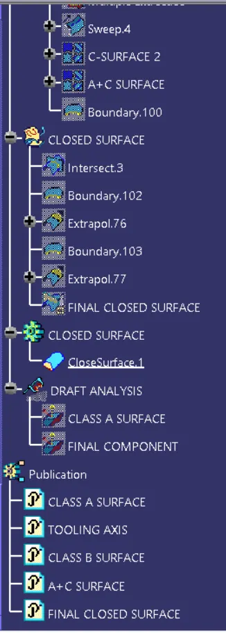
Figure: Expanded Tree(5)