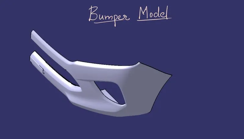
Week 8 - Challenge 4 - Bumper
DESIGNING A BUMPER WITH DRAFT ANALYSIS
CLASS A
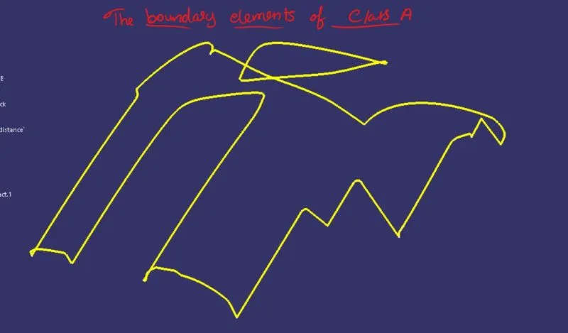
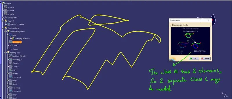
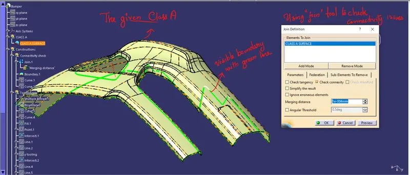
The given Class A surface is checked for connectivity issues using tools like “boundary”, “join”, and “disassemble”. A boundary is created from Class A surface and disassembled to check its sub cells and domain. And Join tool is used to conform merging and connectivity here.
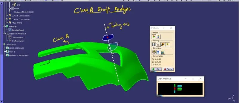
TOOLING AXIS for DRAFT ANALYSIS
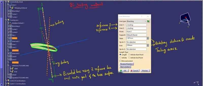
Next step is to create a tooling axis for draft analysis. For this purpose, a geometrical set is created for tooling axis reference construction. Generally, tooling axis is created using bisecting tool taking both extremes of sloping line along the taken reference direction say, z axis of the system. Tooling axis should be oriented in such a way that it offers minimum side core and undercut action and possible to provide draft to every component. Drafting of the component is necessary for proper ejection of molded components and for ease of manufacturing. A minimum of 3-degree draft is required and while designing the components a maximum of 0.003mm limit is said to have for close tolerances like merging surfaces.
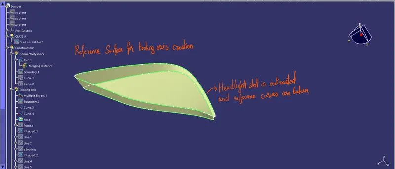
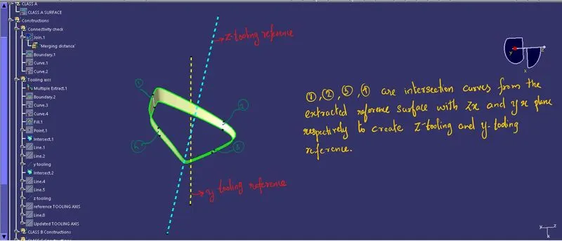
The component here is suitable to have a tooling axis in X-direction in CATIA V5 file.
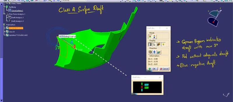
DRAFT ANALYSIS
- Ensure proper workbench (Surface Workbench)
- Ensure material mode is selected in “Custom View Parameters”
- Insert “Feature Draft analysis” from analysis option.
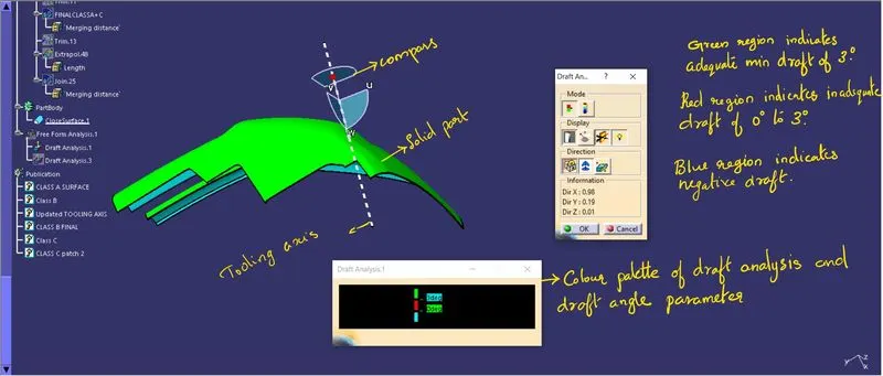
- Select the compass and lock with the tooling axis
- Select the surface to be analyzed and check the parameters for draft angle values
- From the analysis, required changes can be addressed to the Class A surface designer
- If possible tooling axis can be customized again to calibrate minute inadequacies in drafting angle.
- If such an update is operated, make sure to reset the compass after creating the new tooling axis with proper drafting.
CLASS B and CLASS C
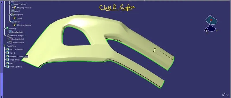
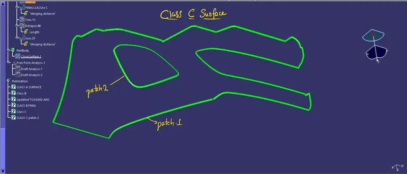
Class B can be termed as engineering surface where all the fixtures and supports of the component need to be designed. Class C surface joins the Class A surface with Class B surface. Generally, Class A and Class C are joined to make one surface which is later trimmed with Class B surface to form a closed surface of the component.
DRAFT ANALYSIS OF THE PART BODY
- Make the solid part using closed surface tool in Part Workbench
- Change to proper workbench (Surface Workbench) for performing draft analysis
- Ensure material mode is selected in “Custom View Parameters”
- Insert “Feature Draft analysis” from analysis option.
- Select the compass and lock with the tooling axis
- Select the part to be analyzed and check the parameters for draft angle values
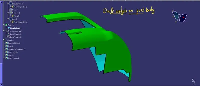
DRAFT ANALYSIS ON DIFFERENT VIEWS
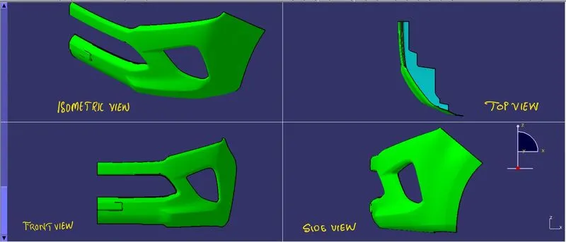
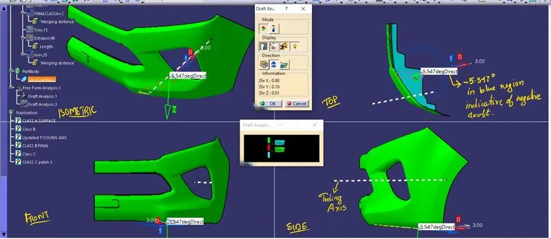
FINAL SOLID MODEL OF DRAFTED COMPONENT