Week 8 - Challenge 4 - Bumper
1. Draft Analysis
The Draft Analysis command enables you to detect if the part you drafted will be easily removed. This type of analysis is performed based on color ranges identifying zones on the analyzed element where the deviation from the draft direction at any point, corresponds to specified values.
For the color ranges there are 3 colors presented in a simpler legend called the quick analysis mode. Beginning with Green, Red and Blue colors corresponds to the draft angle range of above 3 degrees, 0 to 3 degrees and below 0 degrees respectively.
The ideal value of the draft angle is set at 3 degrees and accordingly the component should be representing the green colour all over the surface which indicates the appropriate value.
i. Draft Analysis of the Class A Surface
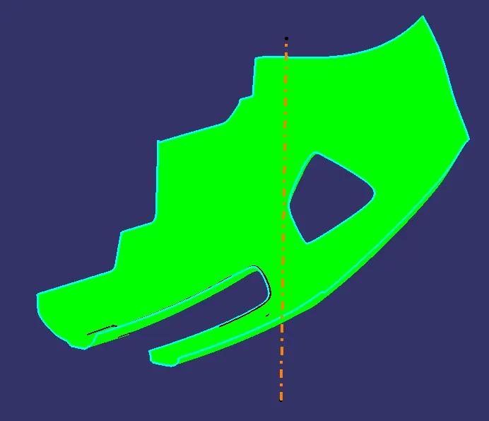
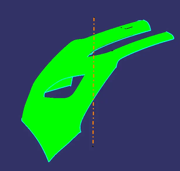
The draft analysis of the Class A is rather simple with a few steps which includes-
1. Select the 'Customize view parameters' from the view options and select 'Material' in the 'Mesh' column.
2. Click on the draft analysis operation either from the Tools option above or from the 'Analysis' bar from the lower column.
3. Place the axis system from the top right on the tooling axis and select the 'Uses the compass to define the new current draft direction' from the direction option in the draft analysis window.
4. Now select the Class A and set the draft angle within the appropriate range (0 to 3 degrees) and identify the color on the surface as to whether it lies within the range or not with the help of .
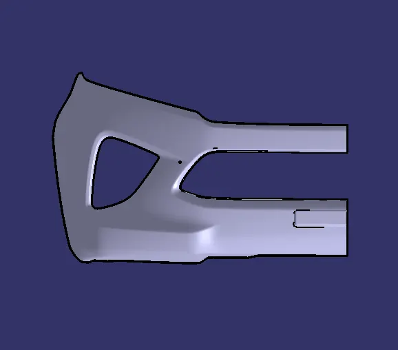
From the above picture the draft analysis of this Class A is successful and lies under 3 degrees.
ii. Draft analysis of Solid Bumper body
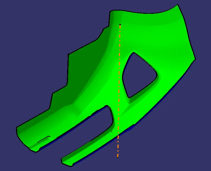
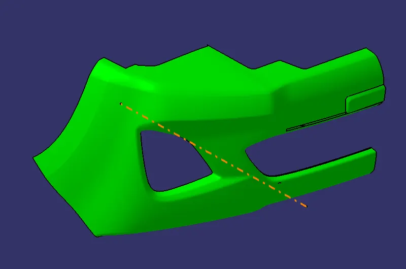
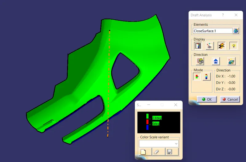
The process of the draft analysis of the solid body is no different from the Class A with similar steps.
After the analysis when we take a closer look there are a few spots on the class C part of the body where the surface is under 2.8 degrees but above 0 degrees.
To fix this we usually change the angle value in the draft analysis window but in this case the C class is not perpendicular to the tooling axis throughout. In most cases where the component is less complex comparitively we adjust the angle value until we achieve a complete green profile.
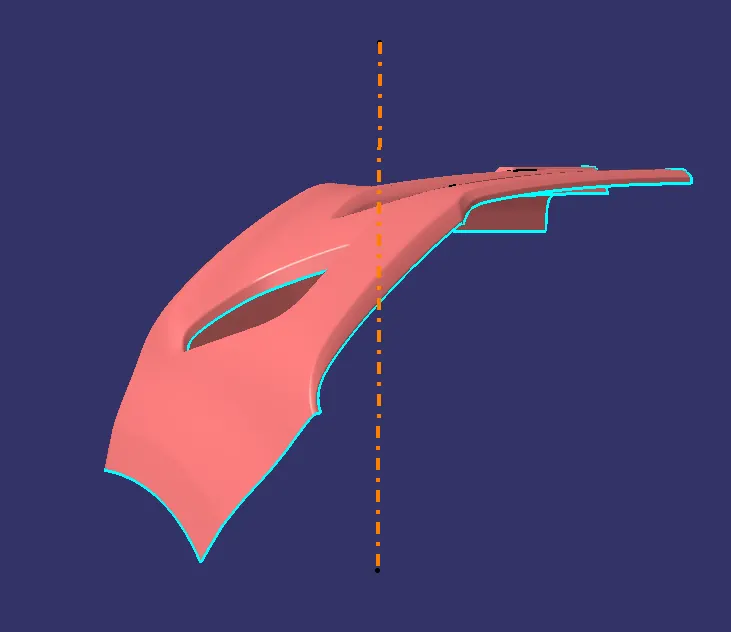
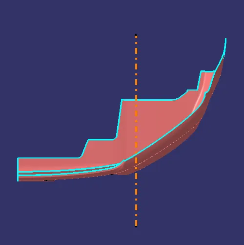
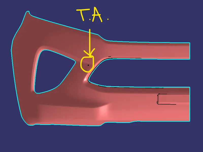
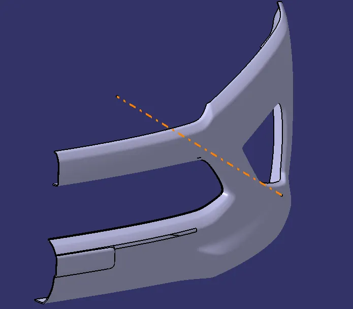
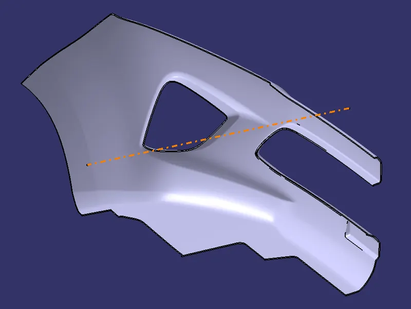
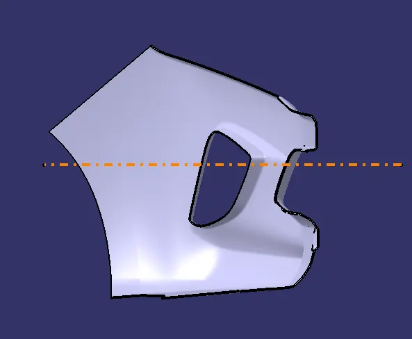
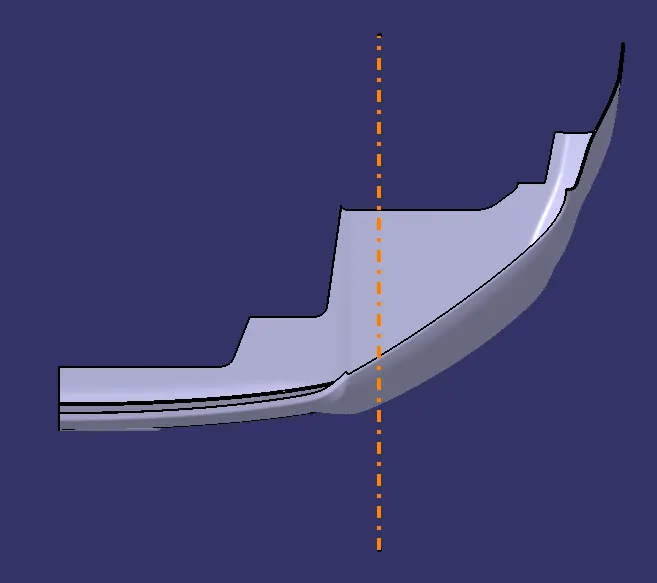
Also the tooling axis created for the bumper is simply in the x-axis since the cross-sections of the class A was so complex.
2. Tooling Axis
3. Solid Bumper
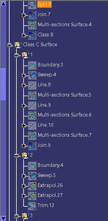
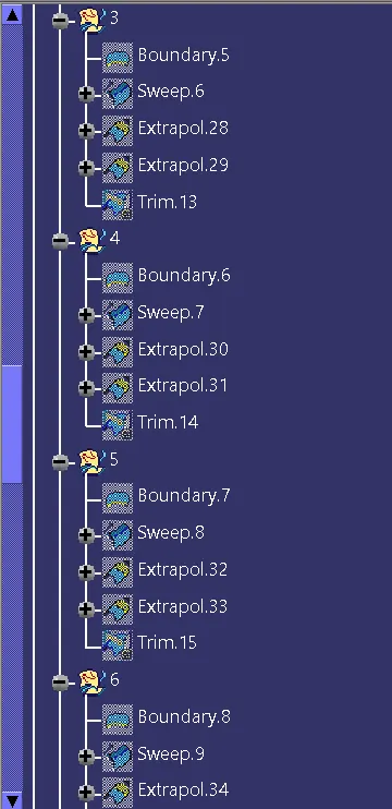
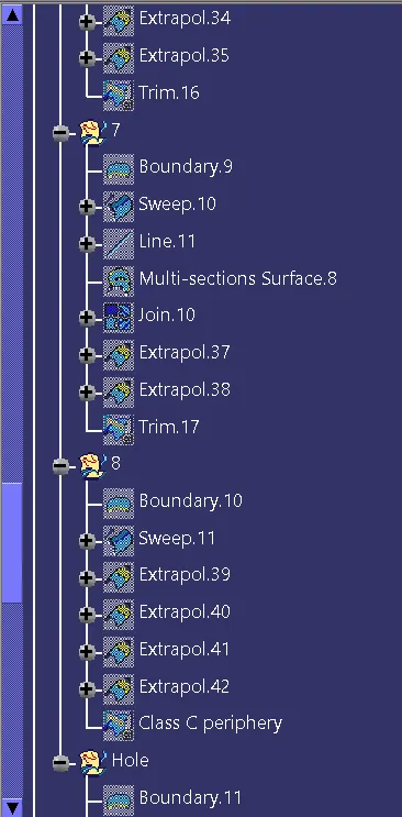
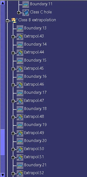
4. Tree Structure
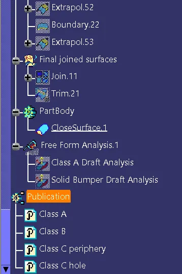
END.