Week 8 - Challenge 4 - Bumper
Q) Creation of Bumper Body with Draft angle
1) Design Check - This includes the checking the given Class A surface for any gaps at the boundaries. There should be no gaps between the surface boundaries.
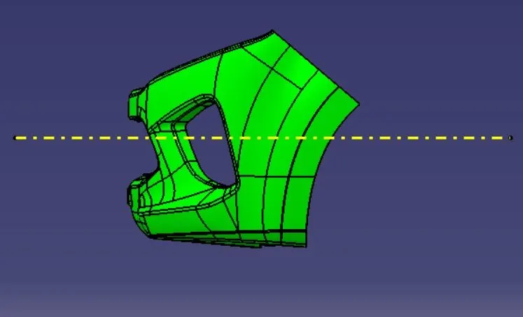
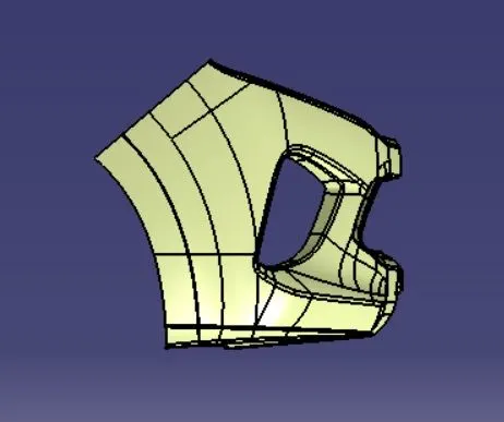
(i) Given Class A Surface
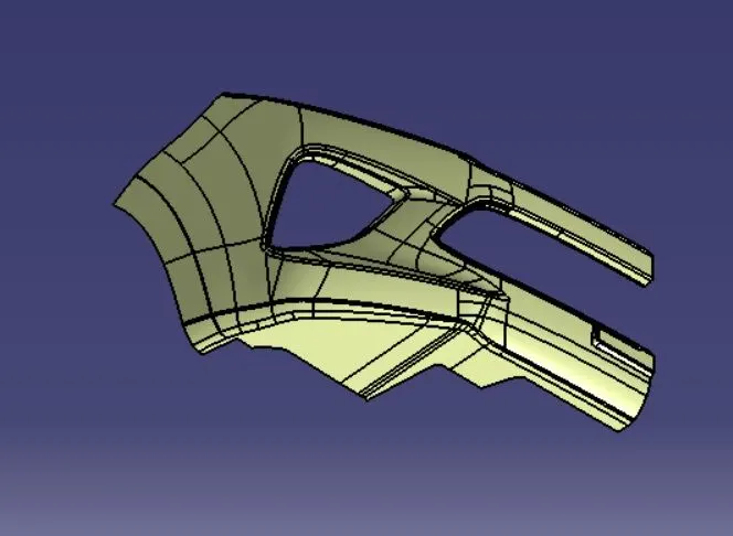
To perform design check operation, select boundary command and click on the given Class A surface.
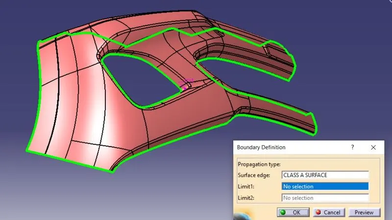
Open surface edges are highlighted in green color, as observed from the figure, there are no surface gaps between boundaries. Therefore, this Class A Surface can be used for further operations of creating tooling direction, Class A , B and Solid body.
2) Creation of Tooling Direction
For tooling axis creation, all the axes directions i.e., x,y and z directions are to be checked for easy removal of the mould and low tooling costs.
(i) X direction
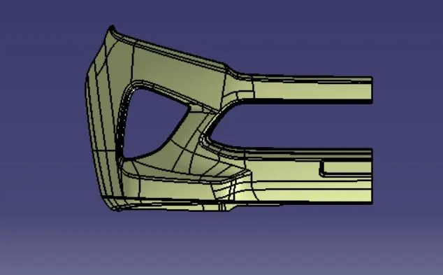
Y direction
Z direction
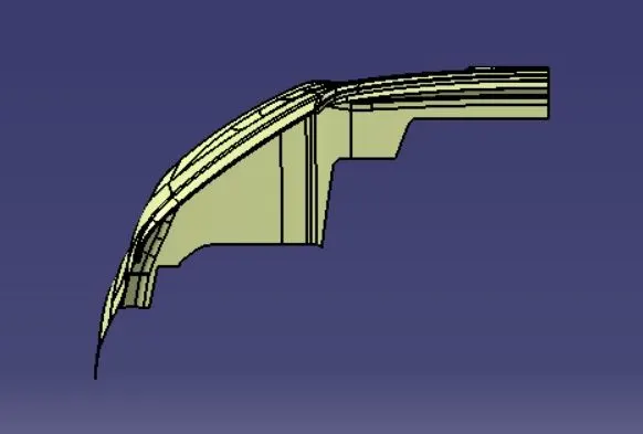
As observd from the above figures with all directions, the hole part is in the X direction and therefore, the X direction is most preferable for the tooling direction.
Clearance of faces is considered for Y direction as more number of faces exist along this direction, these faces aide in creation of tooling direction.
(ii) Creation of Tooling Axis by Bisecting Method
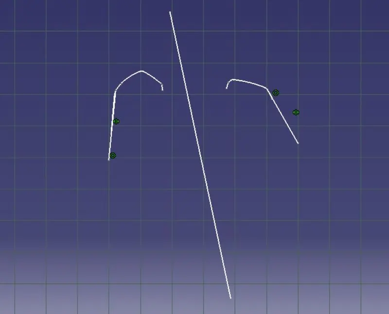
To create a tooling direction, bisecting lines are created using the faces that are closely parallel or at positive draft angles to X direction. Bisecting line is created by intersecting XZ (X direction) plane on the Class A Surface. This bisecting line is the Tooling direction.
(a) Y direction
The face that is perpendicular to X direction can be easily cleared, the faces that are closely parallel to X direction are at a positve draft angle are considered to create a bisecting line. A sketch of XZ plane is considered and is intersected with Class A Surface. A bisecting line generated using the faces that are at a positive draft angle w.r.t X.
b)Tooling Direction
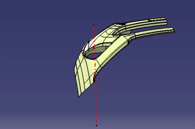
The obtained bisecting line is the tooling direction.
3) Draft analysis
Draft analysis is performed on Class A surface to obtain the Main Tooling Axis. Materials option in customize view should be active before performing Draft analysis. Click on Draft analysis, a color code variant dialog box appears displaying colors, green for positive draft angle, the nominal draft angle for industrial applications is 3 deg. Therefore, 3 deg is provided, the red color indicates a draft angle between 3 and 0. The blue color indicates a negative draft angle.Click on the the compass option on the dialog box , click on the compass and drag it and align it onto the bisector, now click at any point on the surface. The entire surface on topside appears green, this indicates that all the faces can be cleared easily and the bisector created can be considered as the Main tooling axis.
Draft Analysis on CLASS A SURFACE
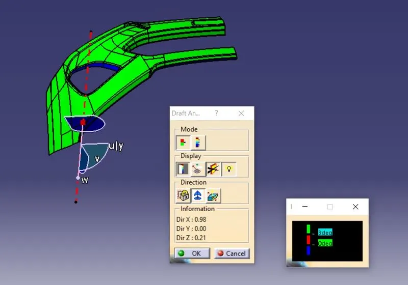
As observed from the figure, all faces are not clearing, some faces have a draft angle in between 3 and 0 (Red color),
some faces have a negative draft angle (Blue color). To solve this, the Tooling axis has to adjusted using trial and error in such a way that all faces are cleared (Green color).
To solve this, the Tooling axis has to adjusted using trial and error in such a way that all faces are cleared (Green color).
Let the X direction be considerd as new tooling direction and perform Draft analysis.
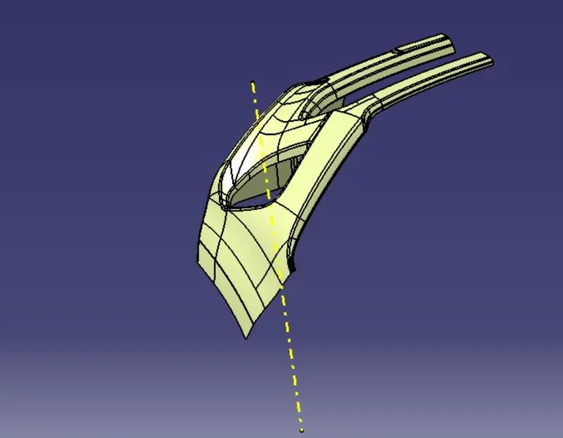
Checking for Draft analysis _ DRAFT ANALYSIS ON CLASS A SURFACE with color code variant
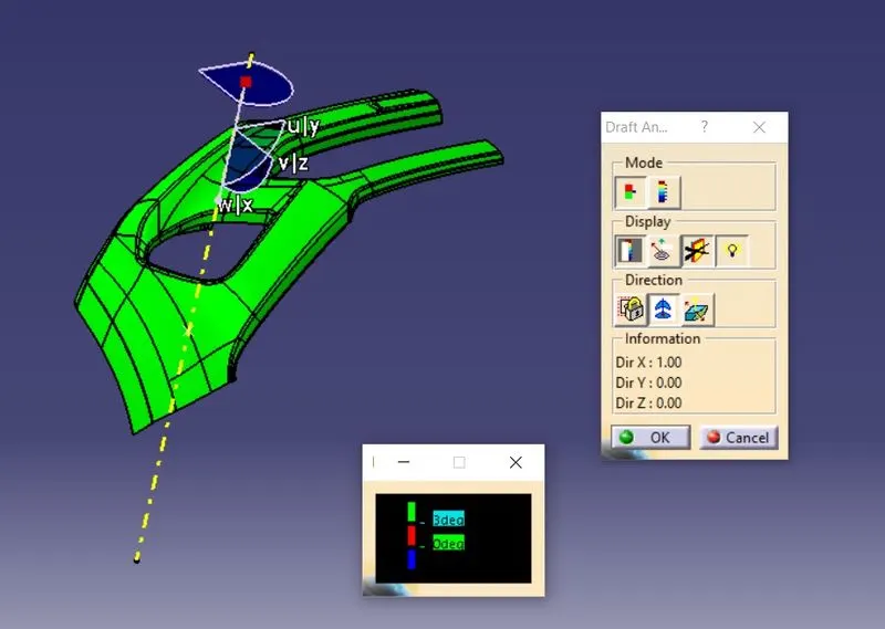
It is evident that all faces are clearing (Green color), therefore, chosen Y direction is exact and ideal to be the new tooling direction.
DRAFT ANALYSIS ON FINAL PLASTIC SOLID BODY
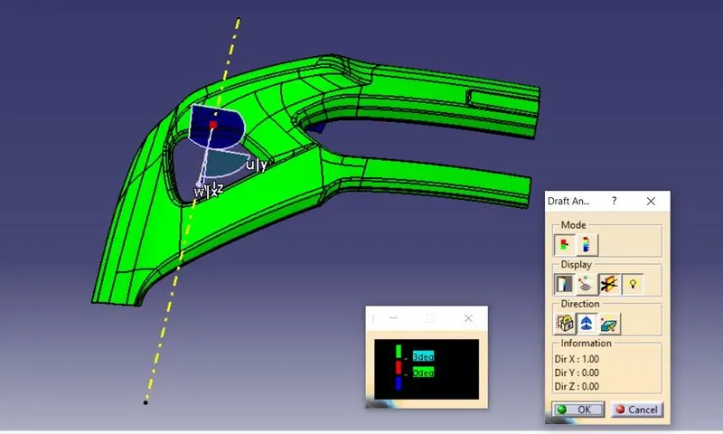
The Draft analysis on Solid Body with color code variant can be observed from the above figure. It can be observed from the figure that all faces that are green in color are cleared with a draft angle of 3 deg.
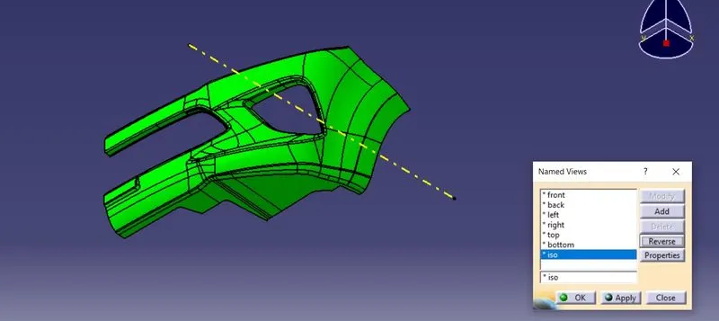
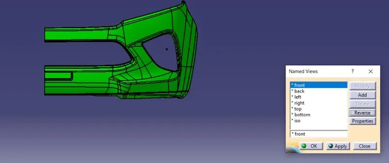
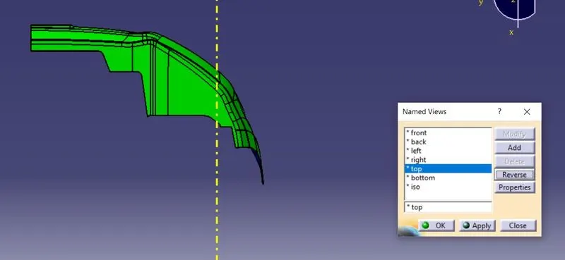
Views of final plastic component
Isometric view
Front view
Top view
Left view
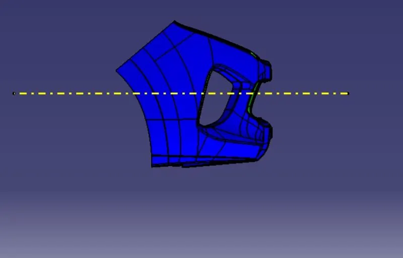
Right view