Week 8 - Challenge 4 - Bumper
AIM:
Constructing a model by making use of the Class-A surface of the bumper that has been provided here. As an added bonus, draft analysis on a closed body can be created by generating a B surface and a C surface.
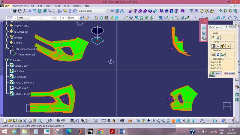
DRAFT ANALYSIS
Using the Draft Analysis command, you will be able to determine whether or not the component that you drafted will be simple to remove. This kind of analysis is carried out based on colour ranges that designate areas on the element that is being evaluated in which the deviation from the drafting direction at any point corresponds to predefined values.
- Go to customised view parameter first, then under mesh, then check material, and then click ok to finish. Do this before proceeding to the draft analysis.
- To view the drafting analyses at this point, navigate to insert » analysis » feature drafting analysis.
- Compass bearings should be used to determine the direction of the draught.
- Adjust the draught angle on the colour scale such that it reads 3 degrees.
- When the passing drafting angle is detected, the component will change from red to green.
- Check the angle of the component with the help of the running point.
Creation of the tooling axis:
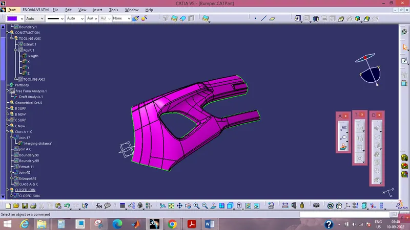
The following is the technique for tooling axis:
- In order to manufacture a plastic item using injection moulding, a Core, a Cavity, and Sliders are required.
- The Core, the Cavity, and the Slider all move and sideways in a specific direction that is referred to as the Tooling Axis.
- Either the Bisection technique or using a Plane as a reference can be utilised for constructing the tooling axis.
In most cases, the tooling axis is conceived of by employing the method of bisecting a line or plane. On the other hand, the tooling axis is assumed to be a line that is normal to the base surface of the bin in those components where it is present. The same approach is taken with regard to this component. Drawing a line that is parallel to the base surface will result in the creation of a tooling axis. The number of offelemts that are allowed should be as low as possible.
In order to determine whether or not a component may be manufactured along the tooling axis, a drafts analysis is run on the class A material. During the process of doing a draught analysis, it was discovered that the bin walls make an angle of ninety degrees with the foundation. There is not a predetermined minimum draft that the walls must adhere to. We are not permitted to make any modifications to the class A surface; however, we are able to notify the class A designer that the walls should have a minimum drafting.
Draft analysis of Class A:
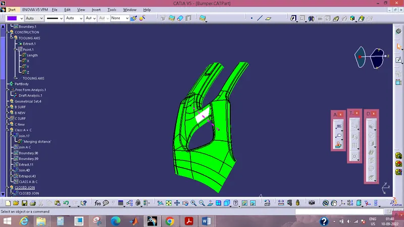
After defining an axis for the instrument, we go on to the drafting analysis. Before we can begin the drafting process, we need to make certain that the materials are selected in the view mode.
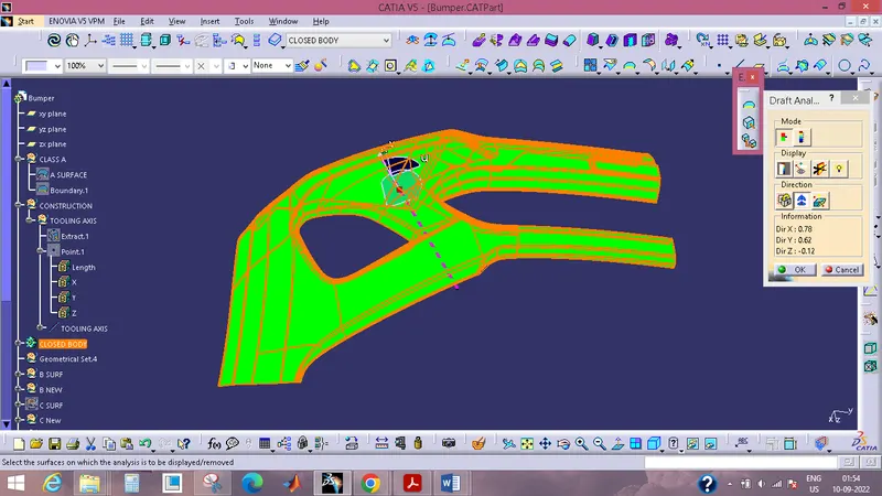
After selecting the feature drafting analysis tool, we move the compass from where it was to where the tool axis is located by dragging it. The compass must then be locked. After that, select any part of the component, and it will provide the result to you.
We adjust the component's minimum drafting requirement to three degrees.
Checking the component's angle can be accomplished through the usage of the running point option.
We even have the ability to change the hue to better suit our tastes.
CLASS B SURFACE CREATION:
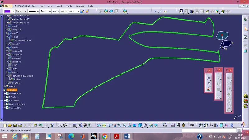
Using the Extract Command, a collection of surfaces were extracted from the Class A surface in order to produce the Class B surface. This is demonstrated in the image below.
It is possible for us to produce a Class B surface by first using the extract command for all of the surfaces that are necessary, and then using the untrim command to restore the surface up to the limit.
Class B Surface refers to the surface at which features such as side walls, base walls, top walls, outer walls, and other such elements are made to accommodate external mountings.
To create a Class B Surface, one must first extract an A Surface, then offset it to the necessary thickness, and finally trim the two surfaces together.
Considering that this is a complex component, we first establish the class B surface, and then we separate some surfaces in accordance with that by assigning some colours to the surfaces for our convenience.
SURFACE OF CLASS C:
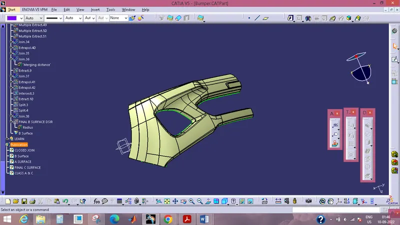
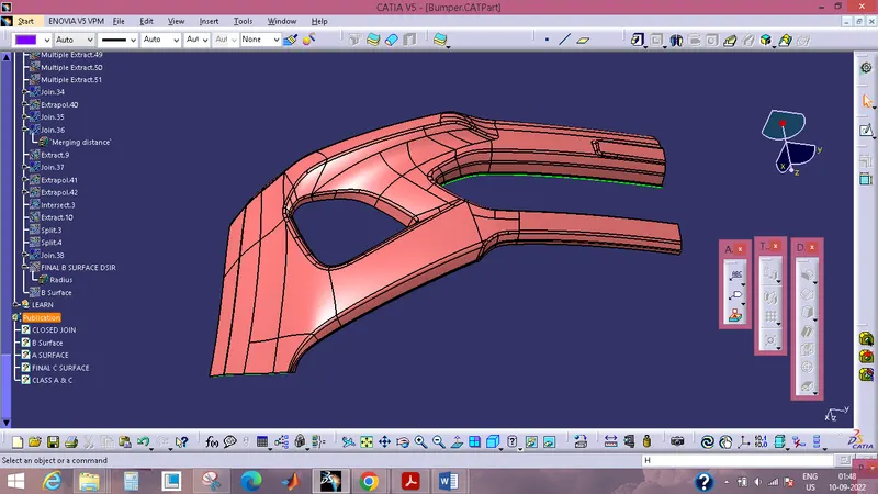
The Class C surface is an intermediate surface that connects the Class A surface and the Class B surface.
When making a Class C surface, the Draft angle and Tooling direction are both taken into consideration.
Now Join C & A Surface:
PART BODY:
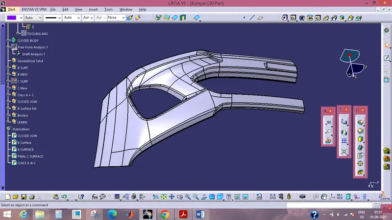
After constructing a closed body, the next step is to construct a solid body by using the closed surface as a starting point. Proceed now to the part workbench in order to create the sloid body by utilising the closed surface command.
DRAFT ANALYSIS:
The highlighted drafting analysis command is used to do the drafting analysis once the development of the solid body has been completed. Simply click on the compass icon, and then drag the compass till it is aligned with the tooling. if the surface is a green colour, the drafting angle is larger than 2.9 degrees (the limit for the green colour is 2.9 degrees), and if the surface is a red colour, the draught angle is less than 0 degrees.
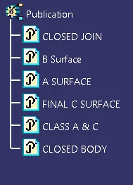
Publications:
DIFFERENT VIEWS