Week 8 - Challenge 4 - Bumper
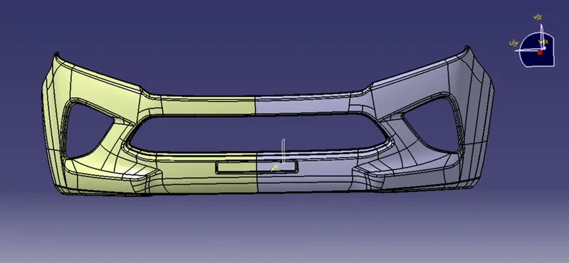
Objective: The main objective of this challenge is to create a solid body of 'Bumper' with the help of the closed surface method by using the 'Generative shape design' workbench in CATIA V5. Performing the 'Draft Analysis' on the solid part body of the Bumper.
Overview:
BUMPER
A bumper is a structure attached to or integrated with the front and rear ends of a motor vehicle, to absorb impact in a minor collision, ideally minimizing repair costs. Stiff metal bumpers appeared on automobiles as early as 1904 that had a mainly ornamental function. Numerous developments, improvements in materials and technologies, as well as greater focus on functionality for protecting vehicle components and improving safety have changed bumpers over the years. Bumpers ideally minimize height mismatches between vehicles and protect pedestrians from injury.
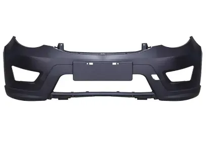
Here in our model Initially, we need to offset the given Bumper class A surface in the inner direction to the required thickness (here the thickness is 3mm). After that, we need to close the patches on the offset surface of the bumper, the patches are formed due to the fillets on the Class A surface. Once all the patches are cleared properly join them together to make a proper class B surface and now sweep the boundary of the class A surface to trim with the class B surface to make a closed body. By using the closed body command in the Part workbench we can get the solid body from the closed surface of the Bumper. Now, again went back to the surface workbench to perform the 'Draft analysis' for the solid body.
TOOLING AXIS:
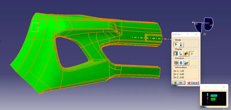
To create the tooling axis, I extracted a surface from class A and created a point in the middle of the surface by using the point command and created a line at that point through the x-axis. Now, I performed a draft analysis check from that line whether the created tooling axis is in the correct position or not. If, in the draft analysis check the surface highlighted with green colour on both sides of the surface the tooling axis is in the correct position and direction.
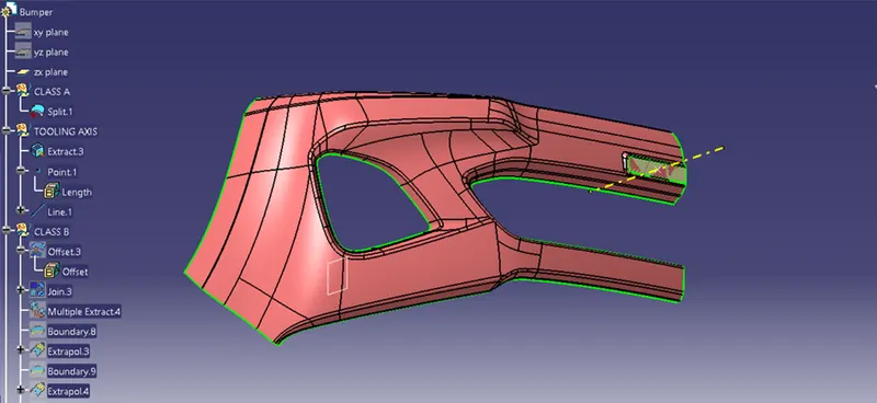
DRAFT ANALYSIS OF CLASS A SURFACE
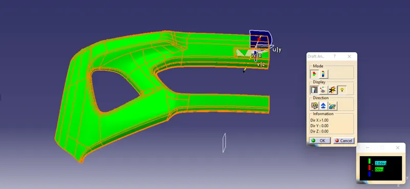
CREATION OF CLASS B SURFACE:
To create the class B surface, offset the class A surface bottom side as per our thickness requirement (here the thickness is 3mm, so I offset the class A to 3mm inside). Once the offset is created, we can observe some patches on the offset surface by taking the boundary for the offset surface, those patches are formed due to the fillets on the class A surface. We need to cover those patches with the help of the multi-section surfaces command by extracting the patch boundaries. Once all the patches on the offset are covered properly join all the patches with the offset surface, to get the replicated surface of the class A surface.
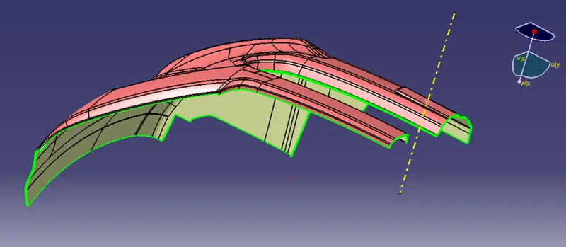
REMOVAL OF PATCHES IN B SURFACE
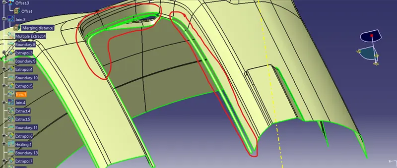
There are 2 methods to remove the patches, As the most of patch comes at the fillet area. So 1st method is to remove the complete fillet area where the patches are coming by JOIN command sub- elements to remove then by extraction of the 2 different surface as fillet area will be the divider.
And then by taking the boundary command extrapolate the surface of both the surfaces and Trim them and finally add the fillet.
2nd method is to take the multiple extract of both side except the fillet then also 2 surfaces will come same as 1st method and repeat the steps.
1st PATCH
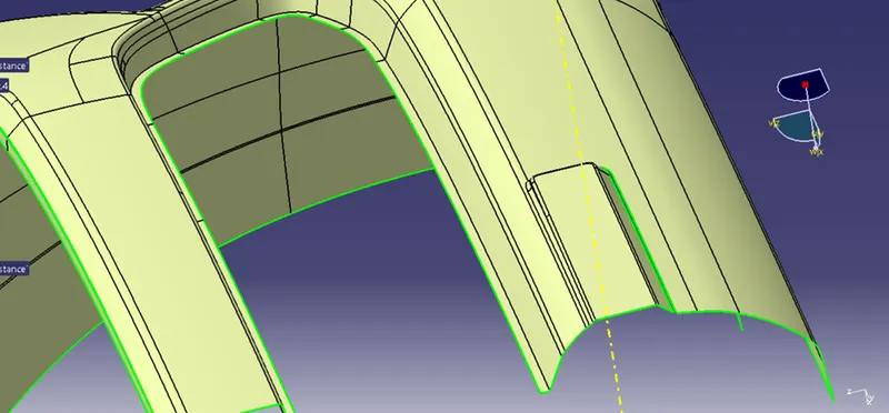
2nd PATCH
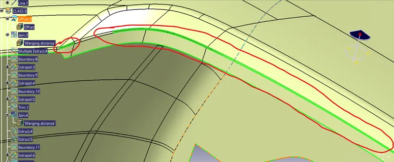
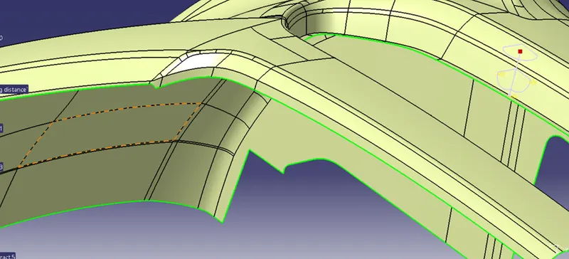
3rd patch
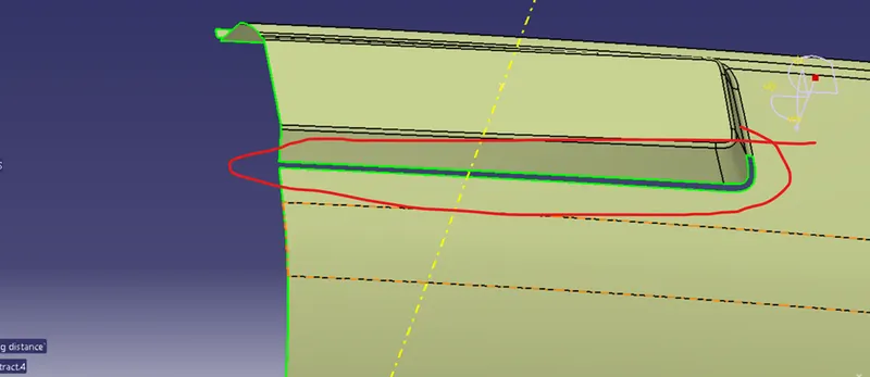
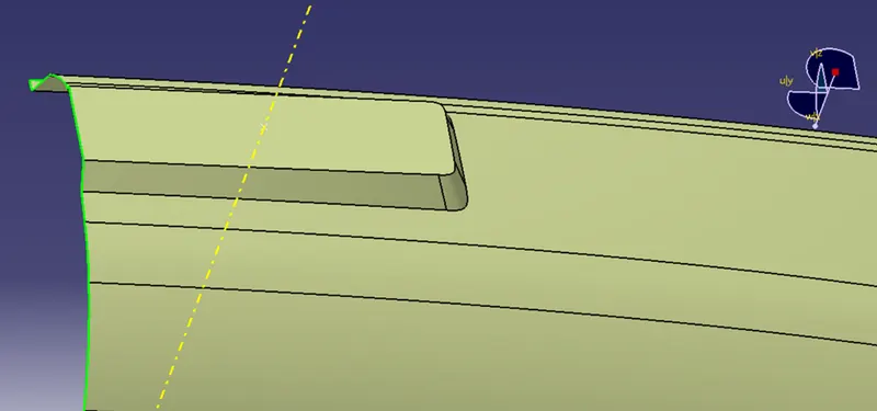
Finally fillets are added as required by the reference of CLASS A surface.
CLASS B Surface
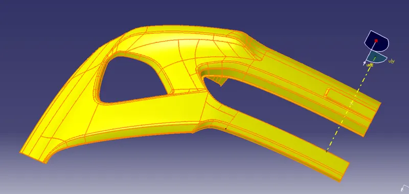
CLASS C SURFACE
To create the class C surface concerning the boundary of the class A surface, I used the sweep command. Initially, I extracted the boundary of the class A surface with tangent continuity, and I sweep the extracted boundary concerning the surface at 93deg (for draft angle) for 4mm to intersect properly with the class B surface. Once we sweep all the surface boundaries of class A, extrapolate the sweeped surfaces until both surfaces got intersected properly, and trim them to remove extended extrapolated surfaces to get a proper sweep boundary throughout the entire surface, including the centre hole of the bumper.
Now, join both class A and sweep boundary to get the complete class C surface.
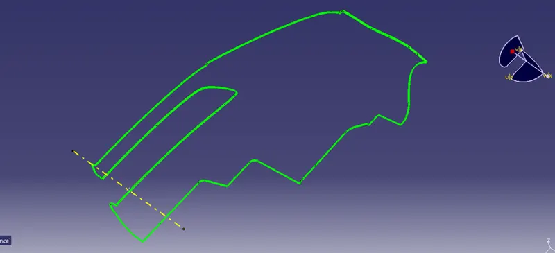
TRIM A+B+C to get the final closed surface .
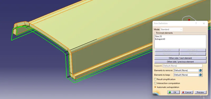
CLOSED SURFACE IN PART BODY
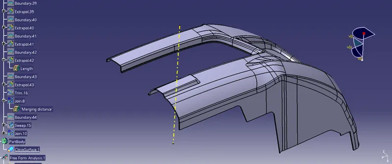
ISOMETRIC VIEW
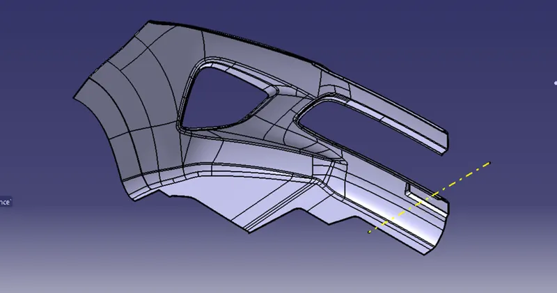
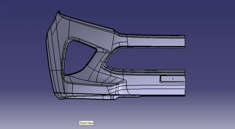
FRONT VIEW
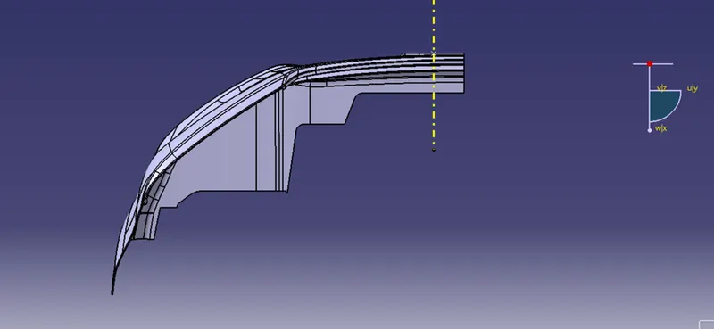
TOP VIEW
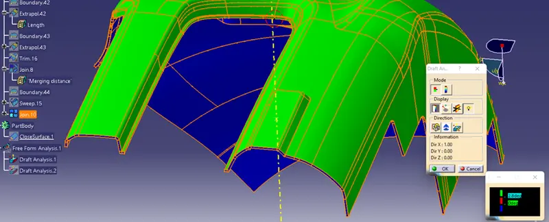
DRAFT ANALYSIS OF CLOSED PART BODY
Steps to do draft analysis
- Step 1: Enter part in Catia.
- Step 2: Go to Material Mode.
- Step 3: Go for draft analysis.
- Step 4: Drag axis bar to the tooling direction of part.
- Step 5: Check for draft and make parting line as per analysis.
Draft angle given is 2.8 degree.
Final bumper