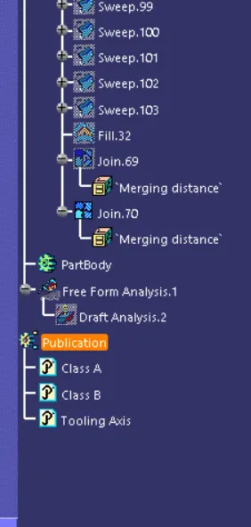
Week 8 - Challenge 4 - Bumper
Design and Draft analysis of a Car Bumper component.
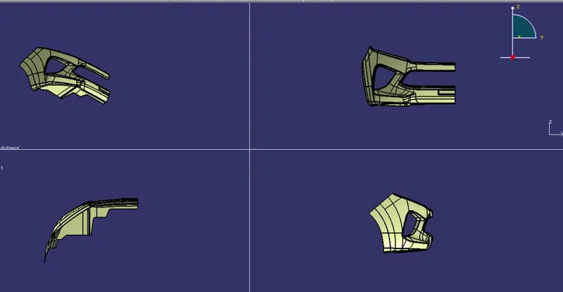
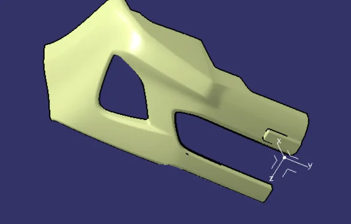
Aim: To Create the Bumper component through the given Class-A surface by creating a required tooling axis.
Procedure for Designing Bezel
To start with is to download and open the below class A file of the bumper.
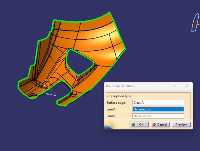
Now check the continuity of the surfaces using boundary option. There should not be not gao between the surfaces.
Tooling Axis / Direction creation:
Once it is verified that there is no gap, next step is to create Tooling axis of the above model. Check visually for the direction of tooling. The should be permissible 3 degree draft angle for the ejection of the part after manufacturing.
For that should create a dummy axis in any direction.
The base of the class A surface is extracted and a point at the center is created and axis system is inserted.
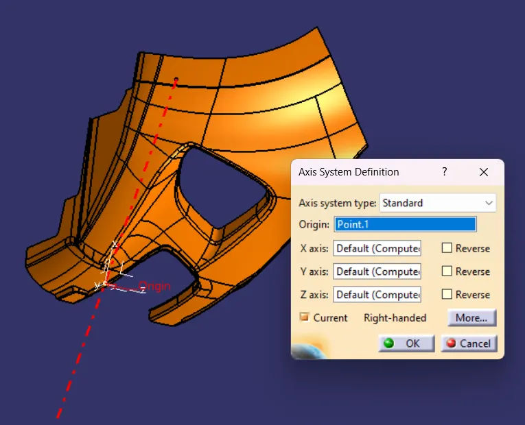
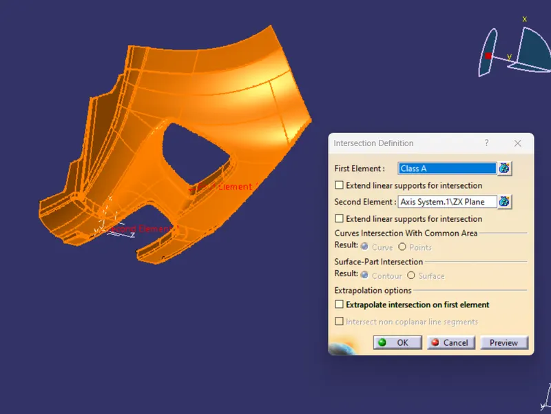
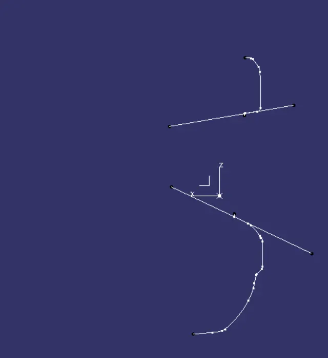
Create a common bisecting line with the halp of two lines created to obtion a tooling axis.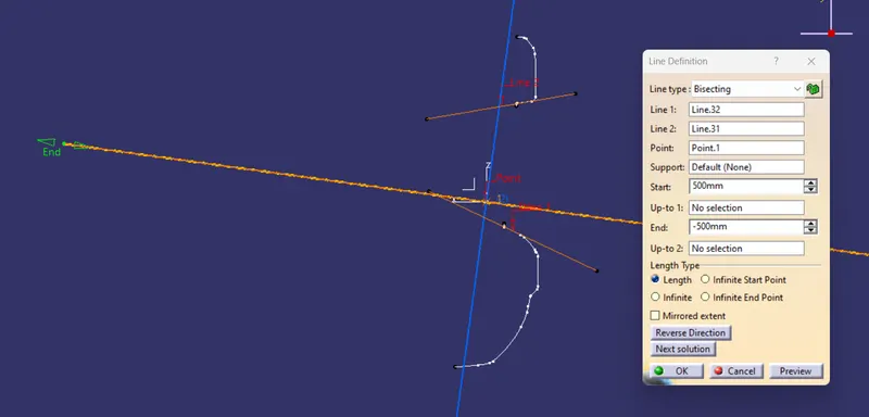
As the tooling axis is created next publish it using publication option in tools section.
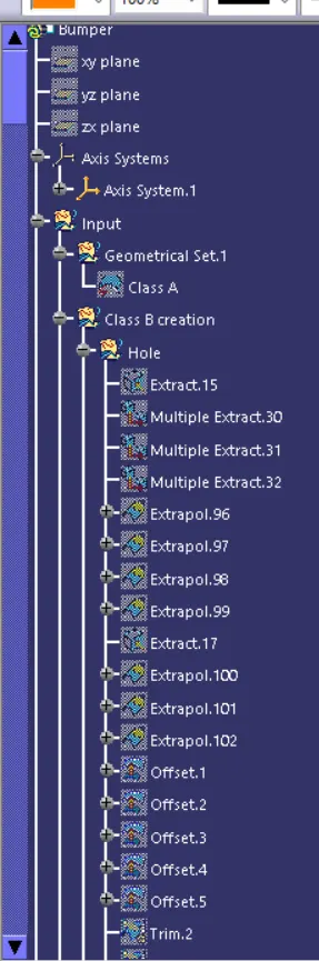
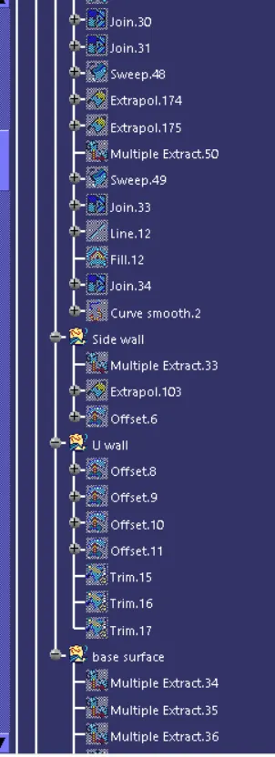
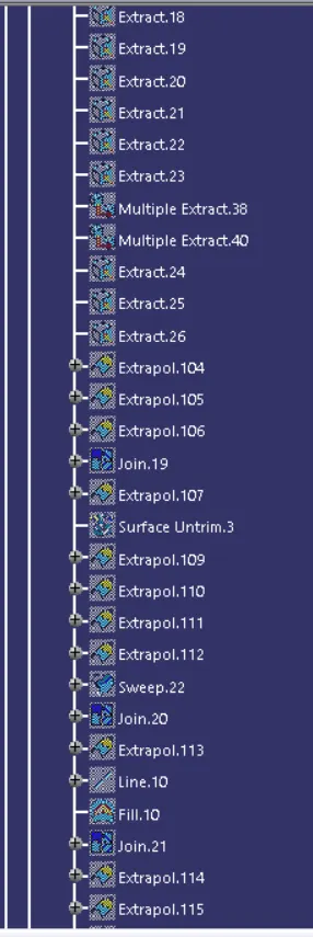
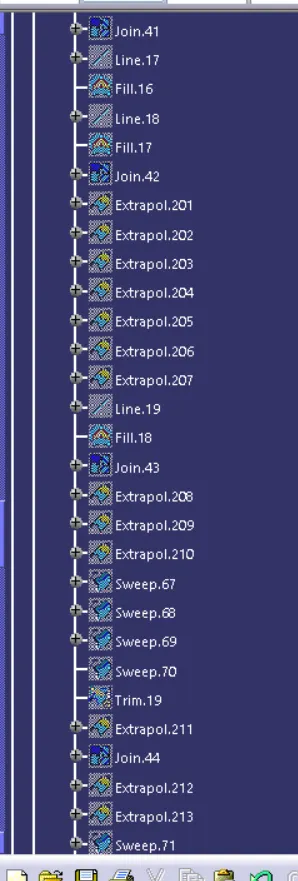
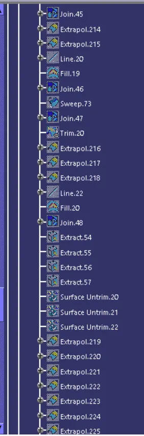
First thing we have to do is to extract the base surface using extract tool  and multiple extract one by one carefully.
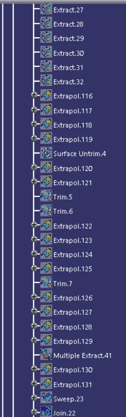
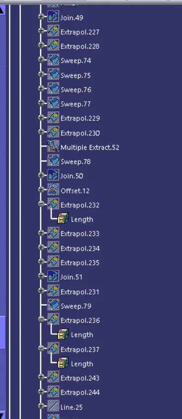
Untrim the surface and extrapolate the walll surface. Trim the wall surfaces as required.
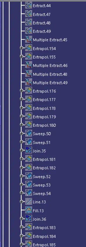
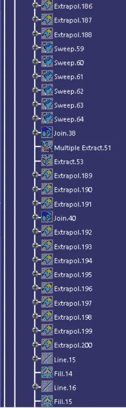
Similarly follow the procedure for all the surfaces and trim them all together.
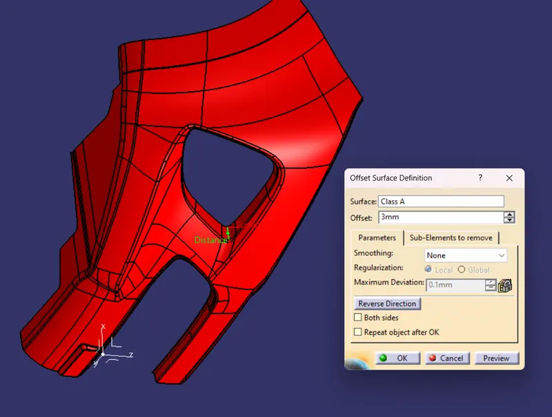
Offset the trimmed surface by 3mm thickness towards outside.
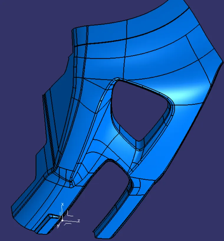
Apply the edges fillet to the edges and check for the fiilet dimension by measurng on the class a surface.
Class C creation:
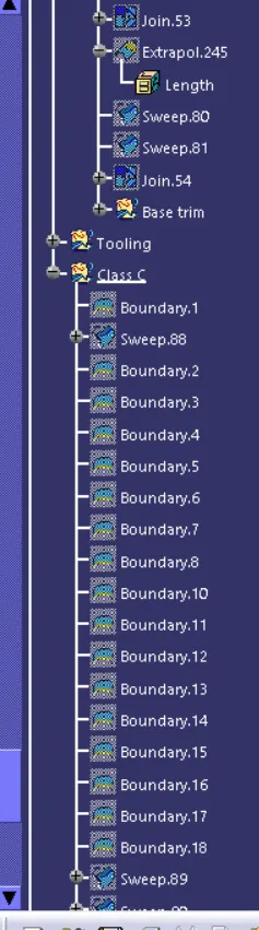
Create the boundary of the class A first
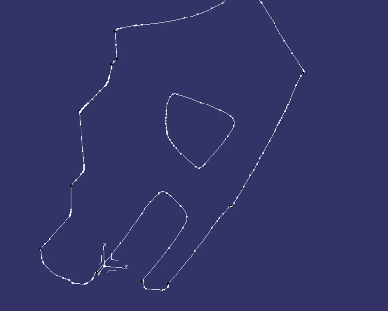
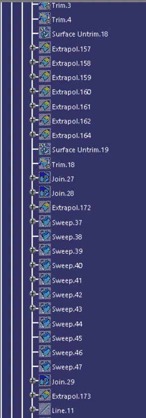
Click sweep option for the creation of the surface. Select subtype "With reference surface", give the angle as 90 degrees and length as 3mm.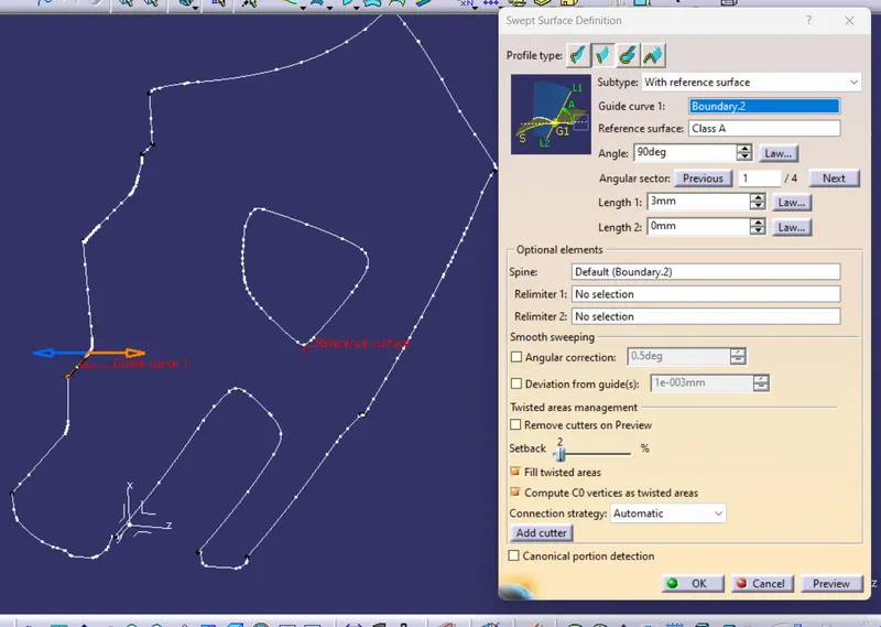
Extrapolate and trim the created class C surface and class B surface for joining accuractely.
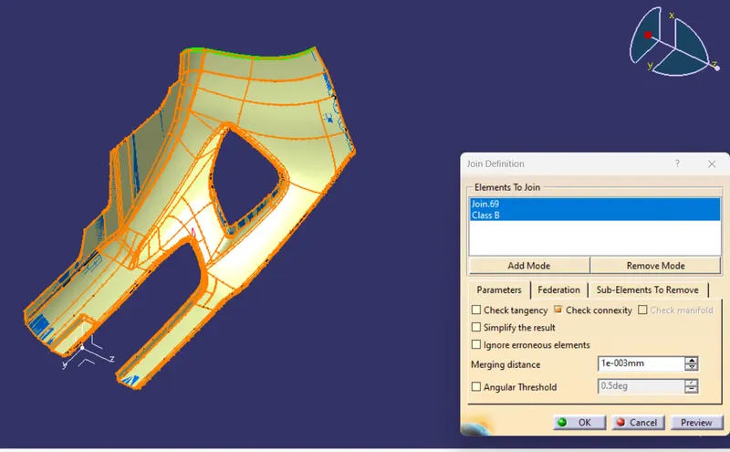
Now join the Trimmed surface with the class A / B surface.
Now check for the boundary if open edges are there or not.
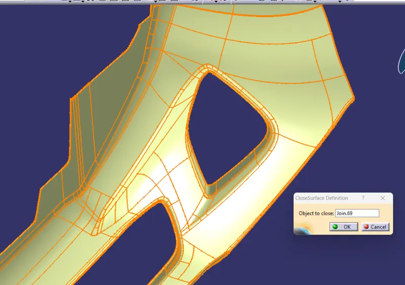
Since there is no open edges, we can proceed to creating solid.
Open part design workbench and click close surface , select the surface body and click ok.
teps for Draft Analysis:
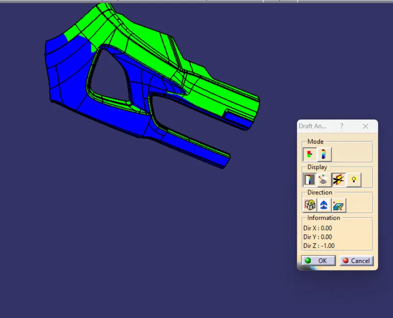
Change the view mode to the custom view and select view paramater as Material mode, then the draft analysis is enalbles.
Click the draft analysis option  , move the compass with the red dot to align with the tool axis.
Now lock the compass and click anywhere on the part, the color will be changed.
Change the value of the green color limit as 3 degrees.
The green color shows that the surface satisfies the draft angle and other color if the angle is not satisfied. This can be corrected by altering the angle and measuring at points to get succesfully draft to get satisfied.
Different Views: