Week 8 Challenge
1.
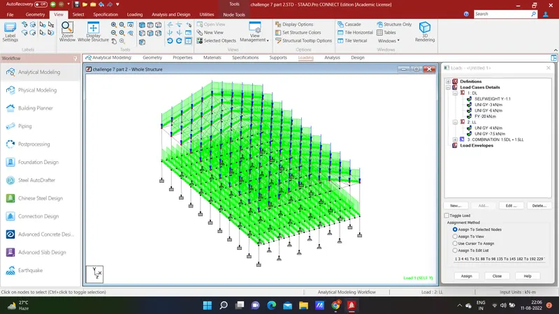
Go to the ribbon toolbar click load case details.
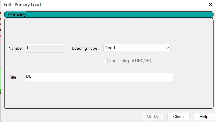
Click primary
Define Load 1 with loading type Dead Load
And title as DL
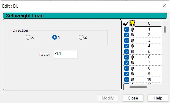
Define Load 2 with loading type Live Load
And Title as LL

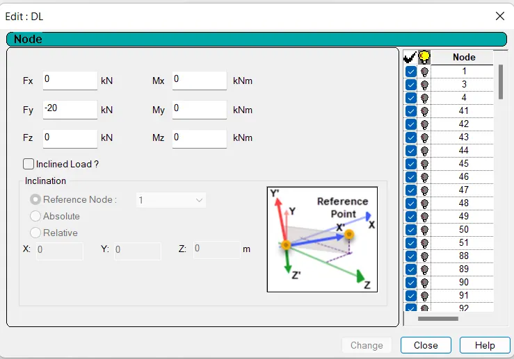
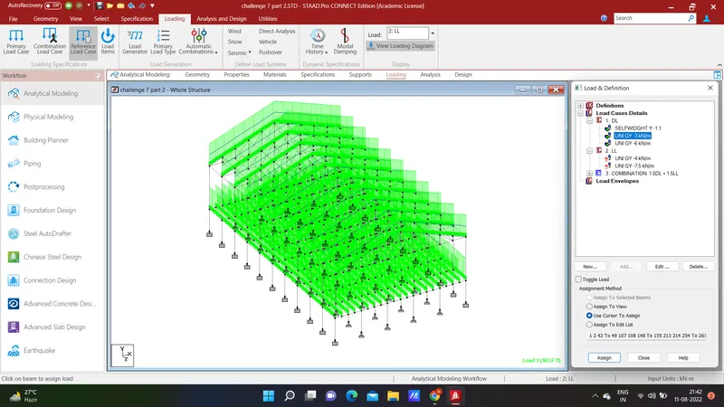
Go to Dead load and add member load
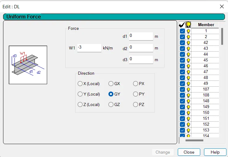
Click uniform force
put W1 = -3 KN/m
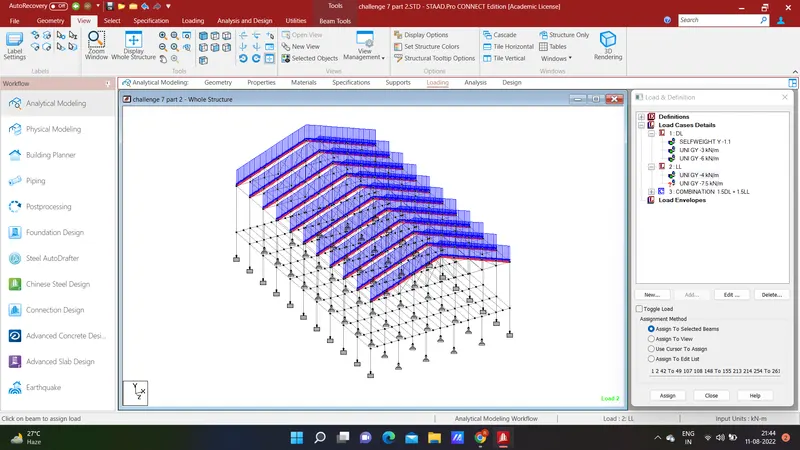
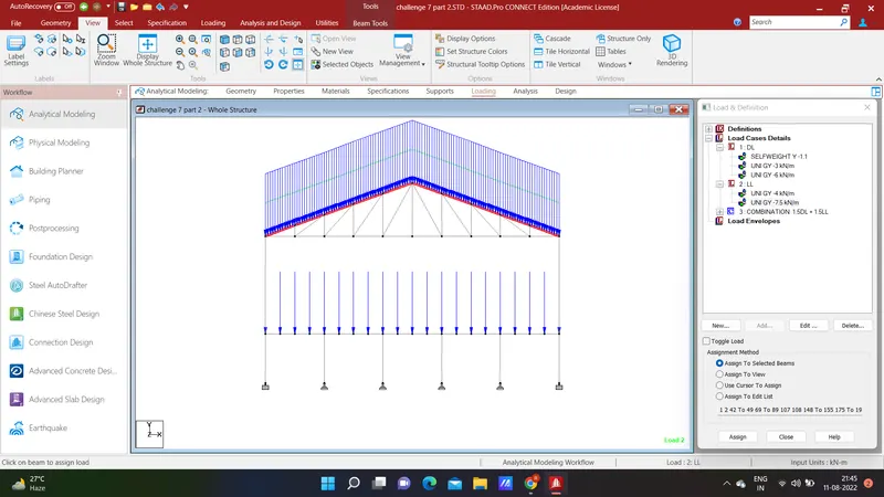
and direction as GY and apply it to the rafter.
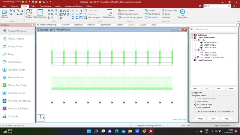
and add remaining member loads in dead load and apply it as given in the question.
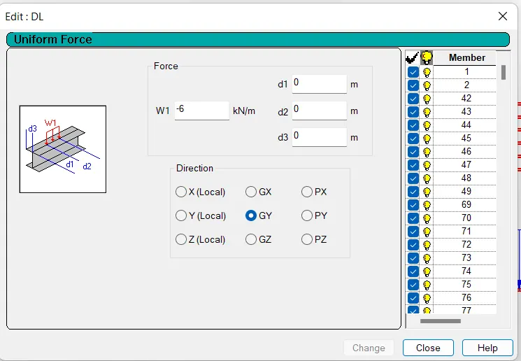
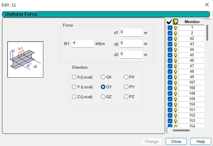
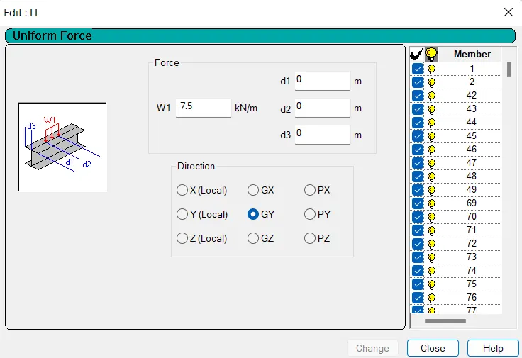
Add member loads in Live Load as given in the question and apply it to respective members.
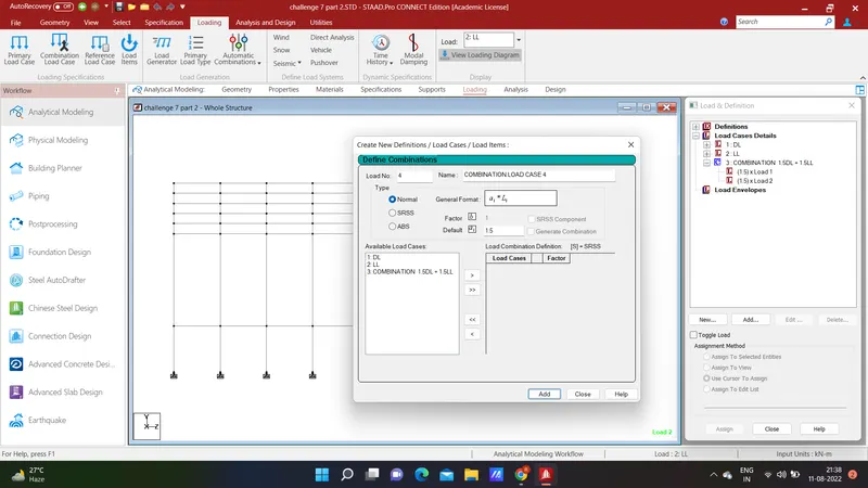
Click on the Combination load case under the loading option and name it as 1.5DL +1.5LL and put load factor as 1.5 for DL and 1.5 for LL.
2.
Go to analysis in ribbon tool bar
define comand
tick all and click add
Result 1 :
The maximum moment in the secondary beam for 1.5DL +1.5LL case is in beam no 75
Bending moment value is M@Z = 53.163 KN-m
go to beam results and click load as combined 1.5DL +1.5LL
Range as group inclined bracing and then ok .
Result 2 :
3.
Go to thegiven attachment
open the model and click on analysis and then click on run analysis option
see the warning in view option
see the instability in the result layout option
choose that and fix it
After all warnings fixed we will run the analysis and see the results
For warning join the nodes 47 and 48 fix it
After run the analysis we found that there is instability occured
go to results view instability for the points
4.
Go to analysis and design and select steel as material
Select IS 800 :2007 code
define design parameters
Apply it on beam and truss element
here we take Lx - not applicable
Ly as a default use for apply to member
Lz as a default use for apply to member
Ky as a factor take it as 1.2 as per IS 800
Kz as a factor , take it as 1.2 as per IS 800
Take utility ratio as 1.2 and apply to the structure.