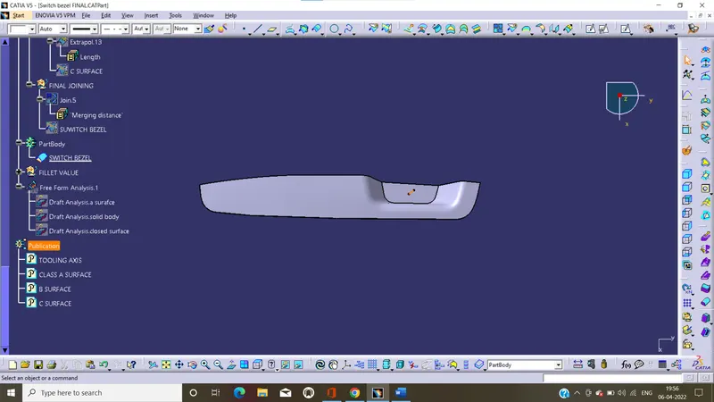
Week 8 - Challenge 3 - Switch Bezel Design
Objective:
To create the tooling axis and perform the draft analysis on switch bezel by using CATIA.
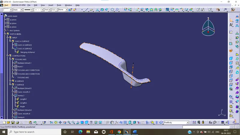
STEP 1 tooling axis creation :
Tooling axis creation
Tooling axis is created to determine the direction of mold open and close. And perform the draft analysis on it.
Creating tooling line Y direction:
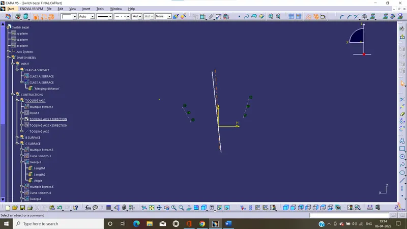
Firstly, we create axis system by using the point i.e... when we create on base surface, after create the intersection curve of class A surface by using ZY planes After analyze the intersection curve we create the two line on intersection curve and by using the lines to create the bisecting line.
Creating tooling lines x direction:
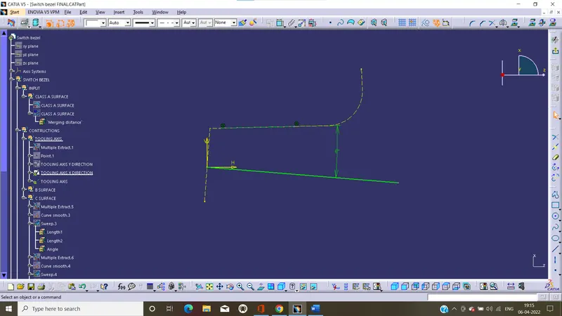
In this we have only one surface. And create the intersection curve by using XZ planes, after creating intersection curve, to draw one line on the intersection curve and draw the second line with by using point. and give the dimension valve between the two line is 3 drg.
Creating tooling axis:
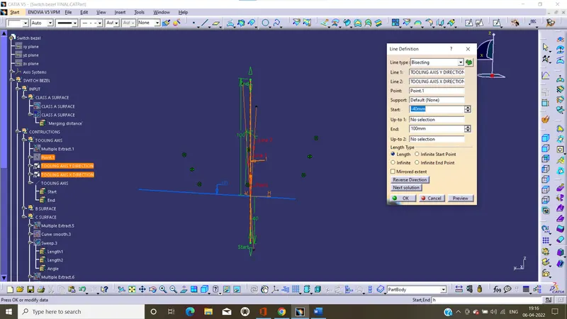
use the two tooling lines along X and Y direction to create the tooling axis by using the bisecting option in line command
Bisecting method:
bisecting line is the line splitting in two equals parts the angle between these two lines. Select a point as the starting point for the line. By default, it is the intersection of the bisecting line and the first selected line.
creating class B surface:
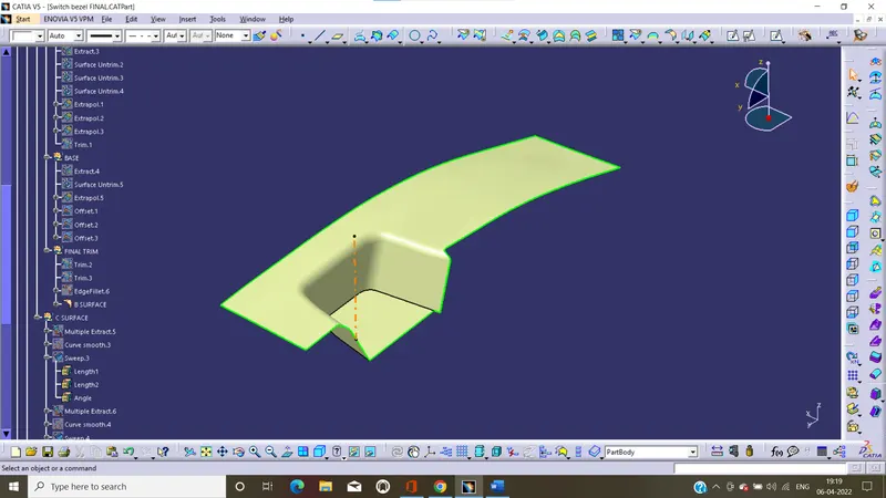
class B surface is created from the class A surface. And the surfaces of class A are extract and untrim it. And extrapolated the untrim surfaces and offset the surface with 2.5 mm in required direction, and give the fillet values to offsetted surface. the final filleted surface is B surface
Creating c surface:
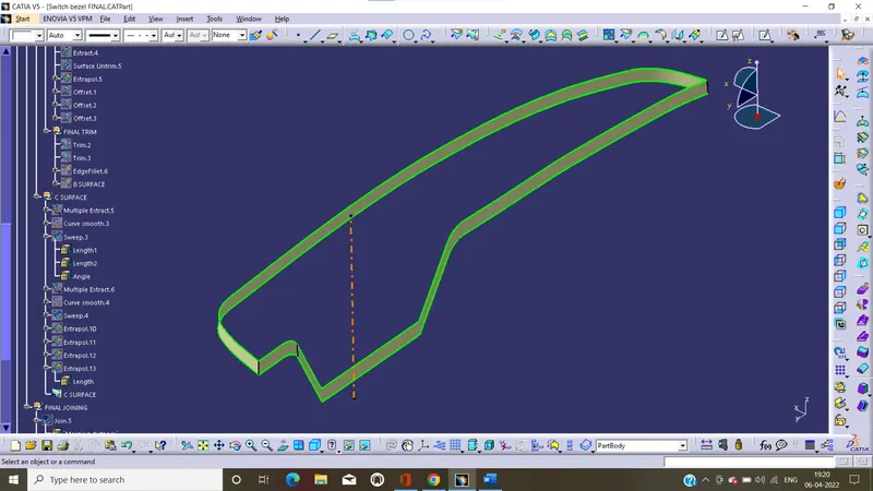
C surface is also created from class A surface. And it will create from boundaries of class A surface. Use the class A surface boundary to performing the sweep operation with 3 deg draft angle along the tooling axis. Use the extrapolate to extract the sweeps and connecting it with the help of trim. The final trim is c surface.
CREATING FINAL SURFACE:
joining the calss A,B and C suraface by using the join command. the final join is closed surface.
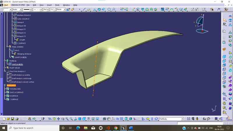
STEP 2 Draft analysis:
Perform the draft analysis on class A surface:
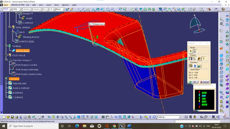
Draft is required on all parts, in direction of mold to release the parts from the mold properly. And draft is the angle in which the part is trapper to release the part easily from mold. Most part are required draft angle is 0 to 2deg. however 3 deg widely accepted.
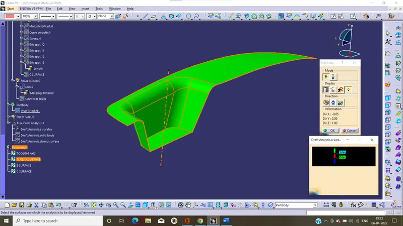
Report
- In this the green color represents the draft angle is greater than the 2 deg.
Class a surface draft analysis different orientations:
isometric:
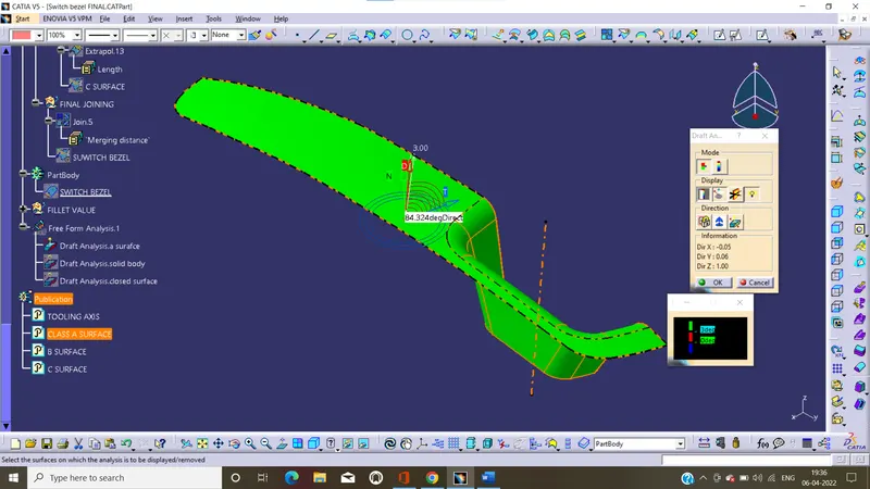
front
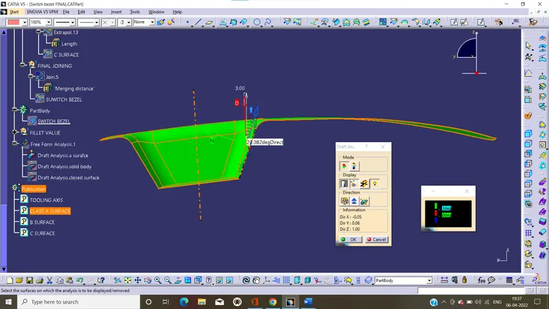
side:
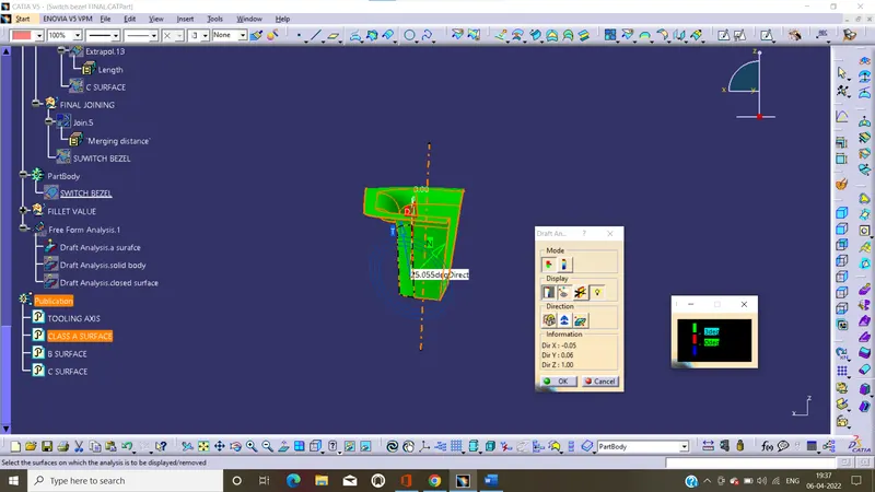
top:
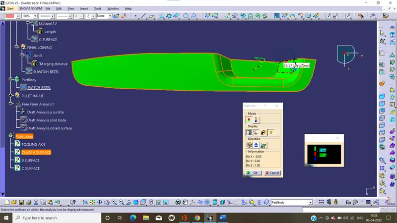
image of color scale verient :
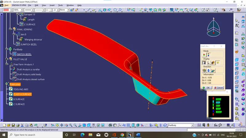
Draft analysis on closed surface:
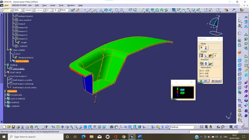
Report :
- In this the green color represents the draft angle is greater than the 2 deg.
- The blue color represents the draft angle is between the 0 to 2 deg.
Draft analysis on plastic component
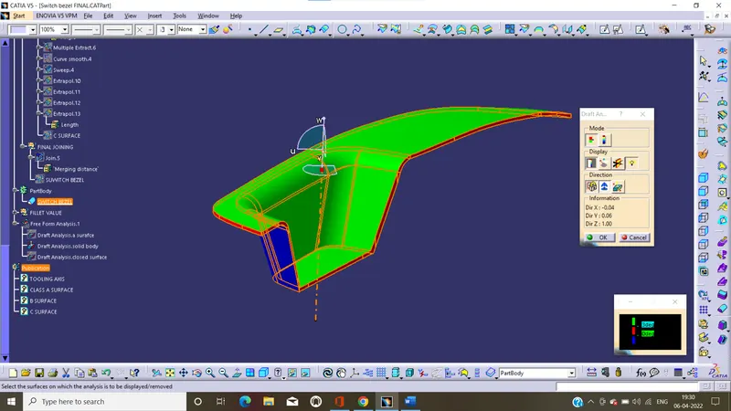
Report:
- In this the green color represent the draft angle is gather then the 2 deg
- The blue color represents the draft angle is between the 0 to 2 deg
- The red color represents the draft angle is lesser then the 0 deg
plastic component draft analysis different orientations:
isometric:
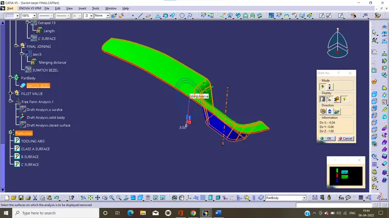
front:
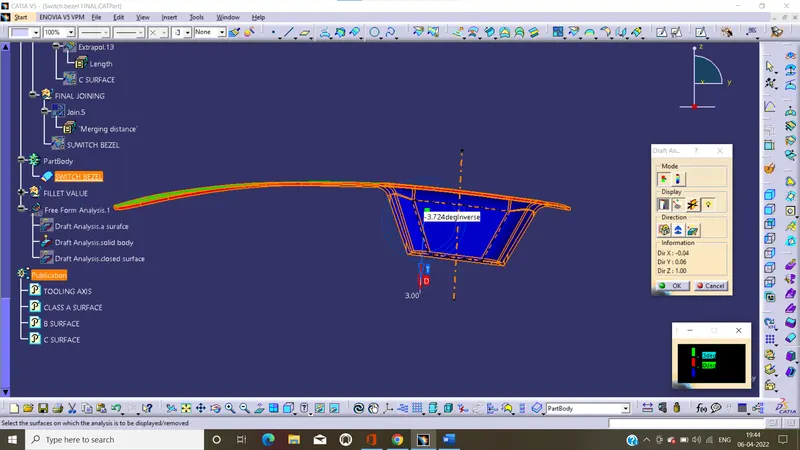
side:
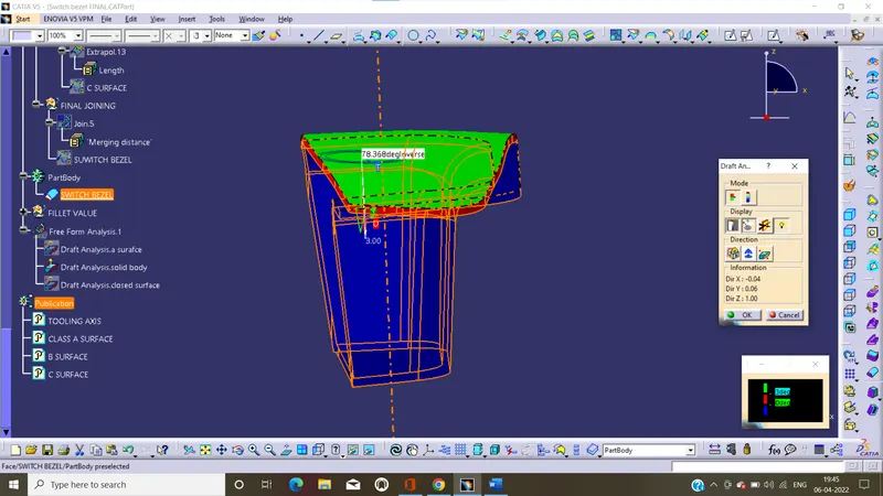
top:
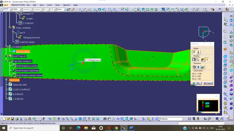
image of color scale verient :
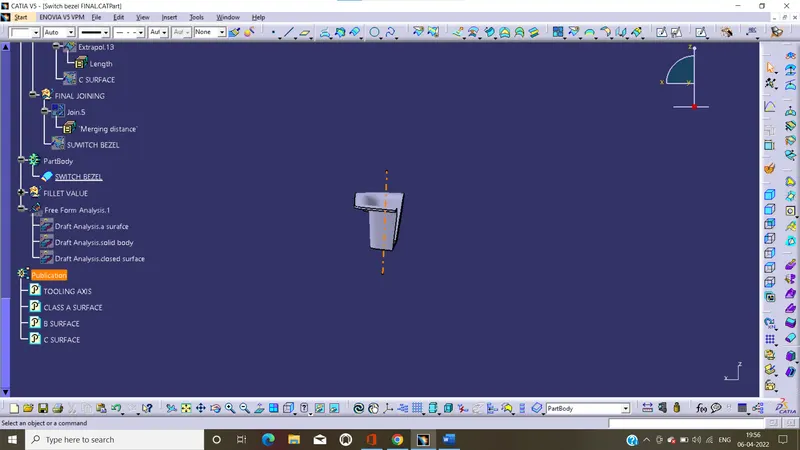
Publishing the base bracket surfaces and tooling axis:
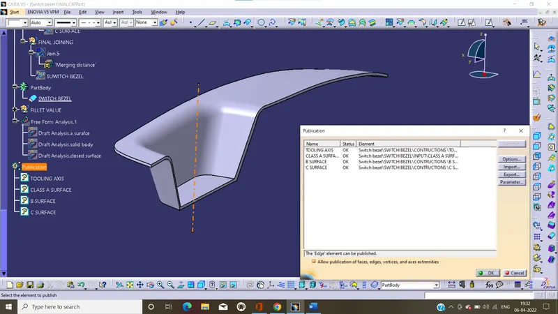
A publication acts as a reference to a geometric or datum entity in CATIA V5. It can use published surfaces that copy the surface name, surface colour and other properties.
solid model:
isometric:
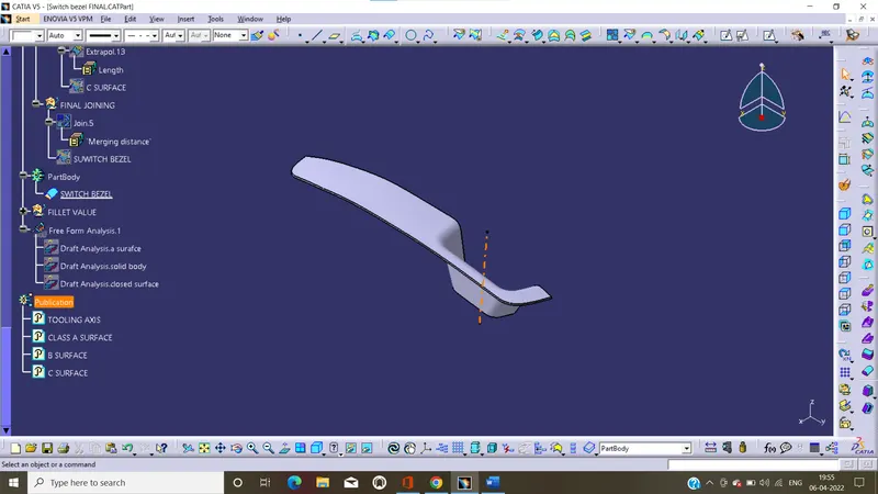
front:
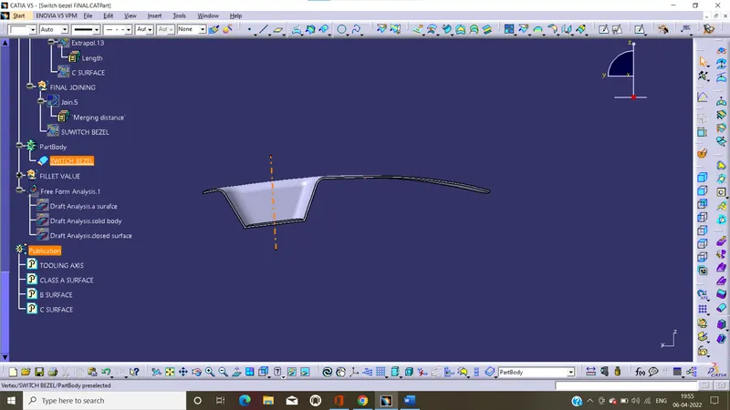
side:
top: