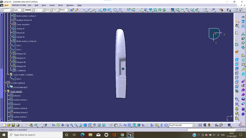
Door Arm Rest Week 8 Challenge
Object:
to creating tooling and side core axis and perform the draft analysis on door arm rest by use catia.
Creating tooling axis:
Tooling axis: the direction of mold open and close and perform the draft analysis on it.
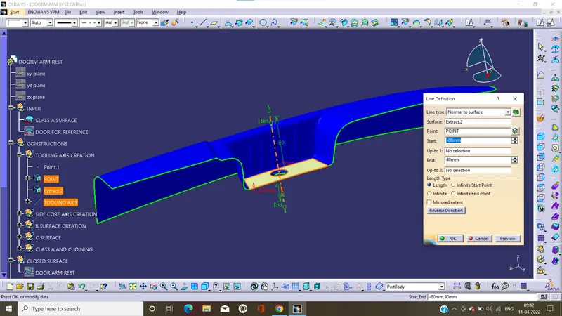
- Firstly, we can extract the base surface and crate a point on it, by use on surface in point command.
- use the point to draw the line, by normal to surface in line command
- That’s the line is tooling axis.
Creating side core axis:
Side core: are additional mechanism it helps to manufacture the component where undercuts can not be avoided. Side core are many used to create the complex geometric of components.
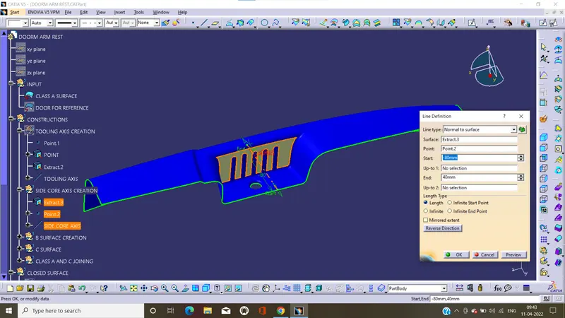
- In this, we extract the side wall or surface (rib surface) and create the point, by on surface in point command.
- use the point to draw the line, by normal to surface in line command.
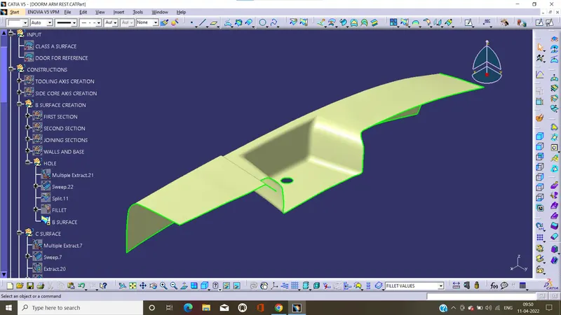
Creation B surface:
Class B surface is created from class A surface. And it is dived into four sets and crate one by one.in fist step we create the front portion of the given surface and second section create the back side of the surface after create them we join it. after extract the side walls and base by using this wall, to trim the joined surface. finally, we get the class B surface with 2.5 mm thickness to class A surface.
Creation C surface:
Class C surface is also created from class A surface but the procedure is not same.in this we do extract the boundaries and sweep them with draft direction in sweep command.in this the guide curve is boundary and the direction is tooling and side core axis when we required. Finally, we get class C surface with 3 deg draft angle.
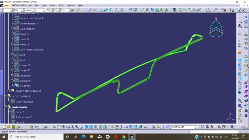
NOTE: in door arm rest we don’t extract the filleted surfaces because it shows an error, in this we use the multi section surface command in surface tool bar and create the filleted surface with required surface.
Join the class A, B and C surfaces:
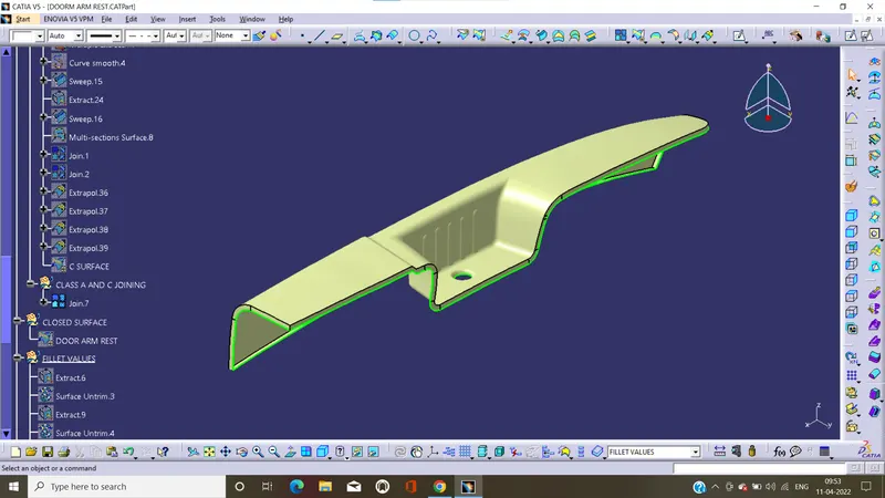
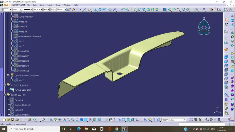
After create all the surface we join the class A and C surfaces, and trim with class B surface. and we get the closed hollow surface.
join class A and C:
Final trim:
Thicken the surface:
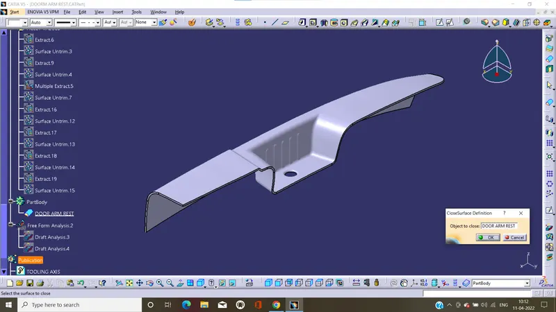
In this, Change the mode to part design and thicken the hollow surface by close body in surface-based tool bar. And we get the solid body with proper dimensions.
Draft analysis creation:
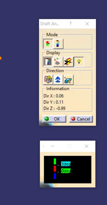
Draft angle: draft angle is required on all parts because to release the component properly with required direction. Most of the components are required draft angle is 0 to 2 deg, however 3 deg widely accepted
In this we perform the drat analysis on class A surface and solid body
Draft analysis on Class A surface:
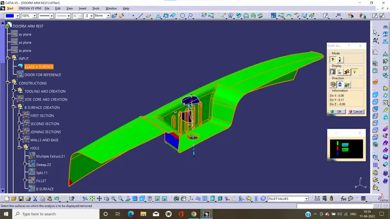
Report:
- In this green color shous the draft angle gathers than the 2 deg.
- The blue color represents the daft angle is between the 0 to 2 deg.
- Red color represents the draft angle is lower than the 0 deg.
isometric:
Front:
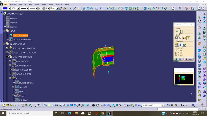
side:
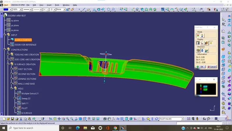
Top:
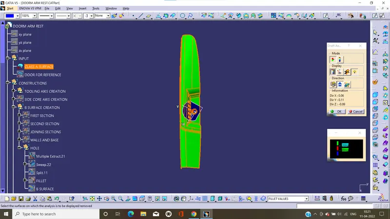
color scale verient:
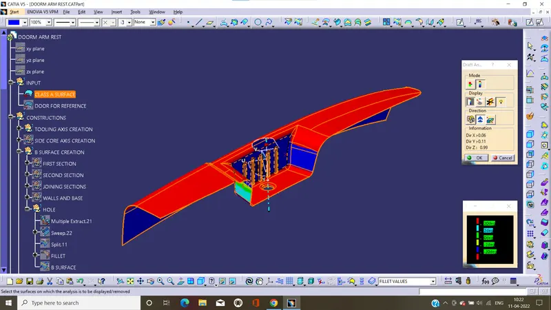
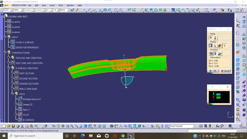
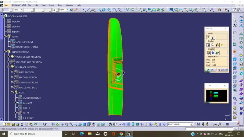
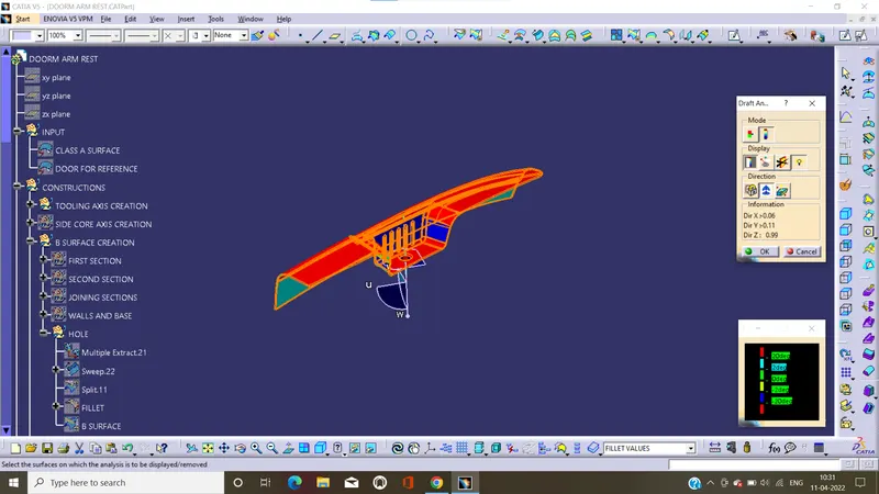
Draft analysis on Solid body:
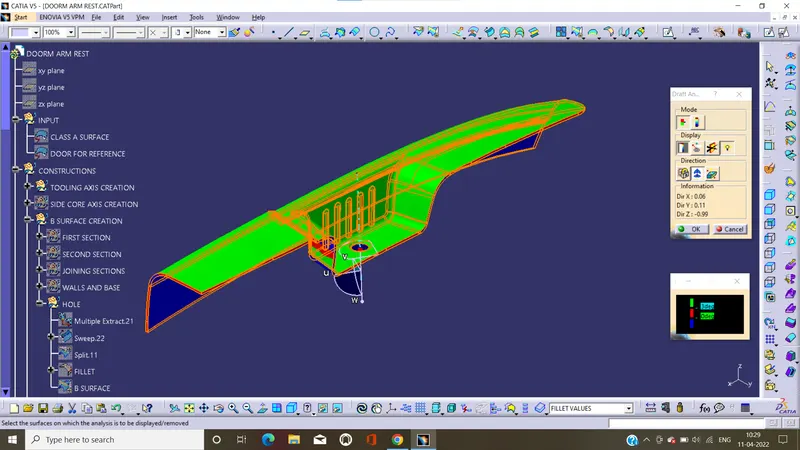
Report:
- In this green color shous the draft angle gathers than the 2 deg.
- The blue color represents the daft angle is between the 0 to 2 deg.
- Red color represents the draft angle is lower than the 0 deg.
Isometric:
Front:
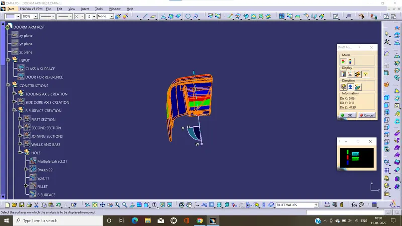
Side:
Top:
color scale verient:
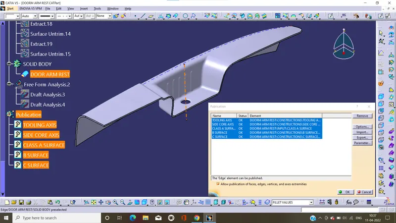
Publication:
Publication acts as a reference to geometry entity in catia.it shows it can publish the surface that copy the surface name, surface color and properties.by use publication to publish the we needed surfaces and to find easily.
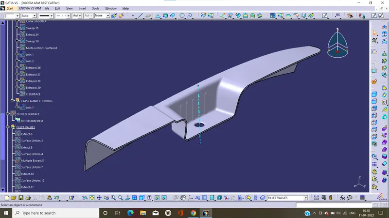
Plastic component different orientations:
Isometric:
Front:
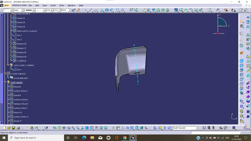
side:
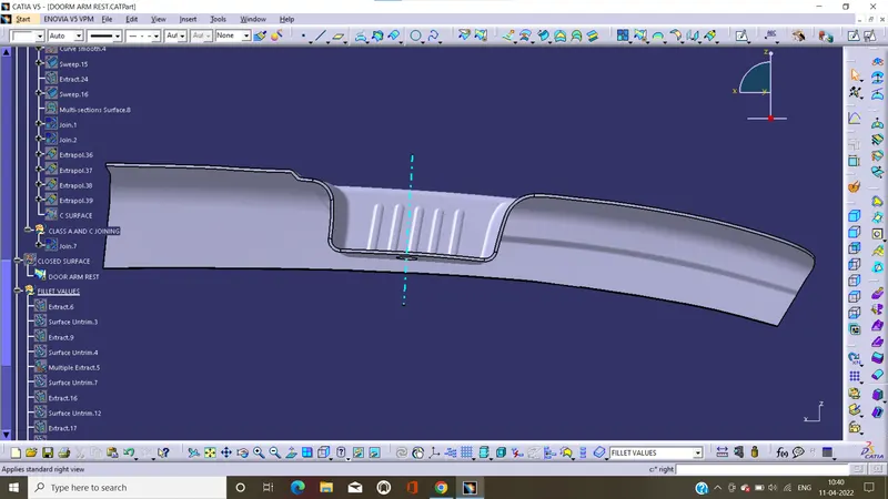
Top: