Week 8 - Challenge 1 - Draft Analysis on a Fan Cover
Introduction :
Drafting analysis helps to detect whether a part drafted will be easily removed from the mold. In Catia draft analysis done by the tool is ‘FETURE DRAFT ANALYSIS’. It will helps to quickly gather the draft angle on multiple surfaces without the need for tedious manual measurements. And it shows the different draft angles and shows if it meets the requirements or not, by various color modes.in this challenge ‘FAN COVER’ is taken as example.
Objective :
To create the tooling axis and perform the draft analysis on fan cover by using CATIA.
Making tooling axis :
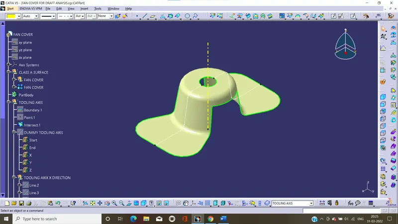
MAKING DUMMY AXIS :
- Check the connectivity of class A surface and just ensure that there is no gapes or openings between the boundaries. If there are more than one boundary because of openings they can also separate.
- In order to perform the other steps, firstly insert the point it can symmetrically center of the part, after insert axis system at the point. The axis system coordinates will facing as same as the default coordinates.
- First determine the correct tooling axis direction need the part.so viewing the part in all directions i.e... x y z. after analyzes the tooling direction, the direction is decided to z axis.
- After determine the tooling axis direction, to make tooling axis we consider the intersection of part in two directions other than the tooling axis.by using xz plane to create intersection curve of the part. And the curve was all most perpendicular or high Angele with the tooling axis than it cannot create problem and they can easily eject. Other hand the intersection curve has some elements are almost parallel or has small angle with tooling axis it should assessed using bisecting line.
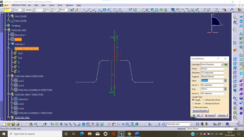
- Before creating the tooling axis, we create the dummy tooling axis. The dummy tooling axis created by using by help of symmetrically center point of the part. And The dummy tooling axis is using the reference axis with the main tooling axis.
Creating tooling axis x direction :
- The intersection curve is created by xz plane.
- After analyze intersection curve, by using faces of intersection curves to create the two parallel lines by using point to point line command.
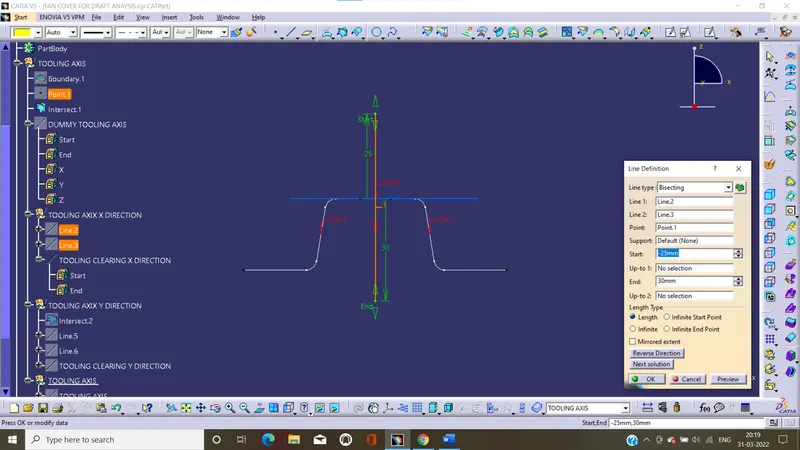
- After creating the two parallel lines, by using these lines to create the axis line along the z direction by using bisecting line command.
- The bisecting line is the tooling clearing axis, and it is created by the direction x.
Creating tooling axis y direction :
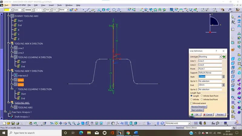
- Intersection curve created by the zy plane.
- By using faces of intersection curve to create the parallel lines by using point to point line command
- After creating parallel lines, using these parallel lines to create tooling axis along the z direction by using bisecting line command.
- The bisecting line is the tooling clearance axis, and it created by the direction y
Creating tooling axis :
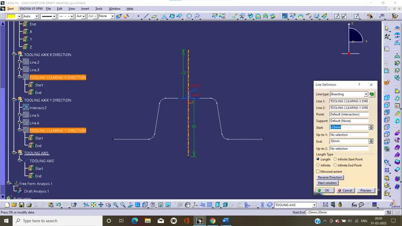
- By using the to two tooling clearance axis x and y direction, use the bisecting line to create new line i.e... tooling axis and select the required direction and create the tooling axis.
- We get required bisecting line, and change the bisecting line name to tooling axis.
- And also change the color and thickness of the line for better visibility.
Bisecting method :
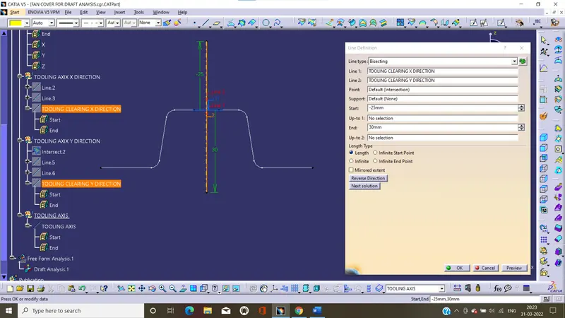
bisecting line is the line splitting in two equals parts the angle between these two lines. Select a point as the starting point for the line. By default, it is the intersection of the bisecting line and the first selected line.
Publishing the fan cover and tooling axis:
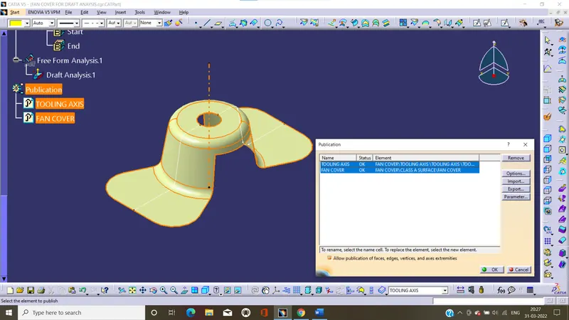
A publication acts as a reference to a geometric or datum entity in CATIA V5.It can use published surfaces that copy the surface name, surface colour and other properties.
Draft analysis :
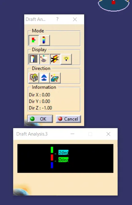
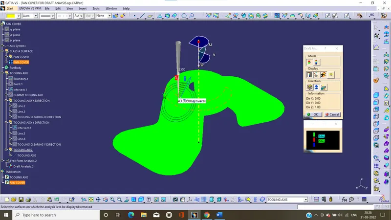
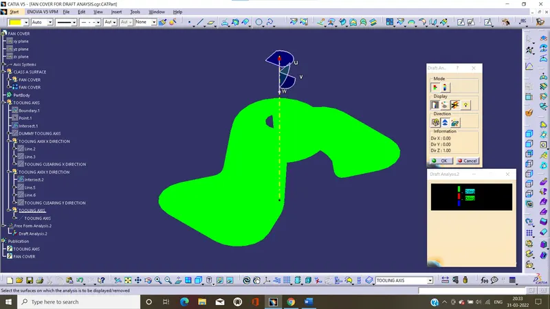
- This type of analysis is performed based on colour ranges identifying zones on the analysed element where the deviation from the draft direction at any point, corresponds to specified values.
- The maximal draft analysis accuracy is 3 deg. and minimum are 0.01 deg. In this case consider the 3 deg angle for this class A surface.
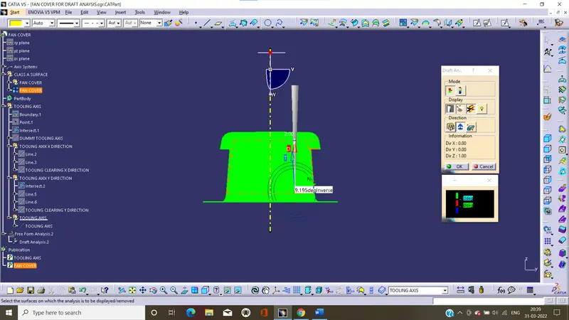
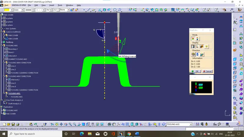
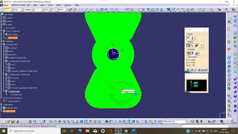
- In this all surfaces are green that is the surface has enough draft angle
- The draft analysis is concluded that the direction of tooling axis is correct position and meets the required draft angles considerations.
IMAGE OF COMPLTE DRAFT ANALYSIS
IMAGE OF COLOUR SCALE VARIANT
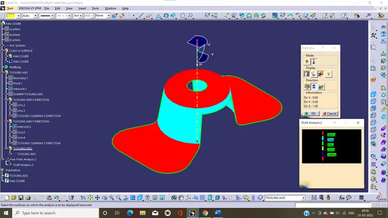
DRAFT ANGLE IN VARIOUS ORIENTATION