Photo Realistic Rendering
Modeling Of American Chopper In Solidworks
OBJECTIVE:
- to create the individual parts of chopper by using solidworks 2020
- assemble tha all parts of chopper
- know tha application of decals,lights,views etc...
- to create the relastic images and renders by using photoview360 and solidworks visualize.
INTRODUCTION:
A chopper is a type of custom motorcycle which emerged in California in the late 1950s. A chopper employs radically modified steering angles and lengthened forks for a stretched-out appearance. They can be built from an original motorcycle which is modified ("chopped") or built from scratch. Some of the characteristic features of choppers are long front ends with extended forks often coupled with an increased rake angle, hardtail frames (frames without rear suspension), very tall "ape hanger" or very short handlebars, lengthened or stretched frames, and larger than stock front wheels. The set of tubes that connect the rear fender with the frame, and which are often extended several feet high, is a signature feature on many choppers.
DESIGN METHODOLOGY/APPROACH:
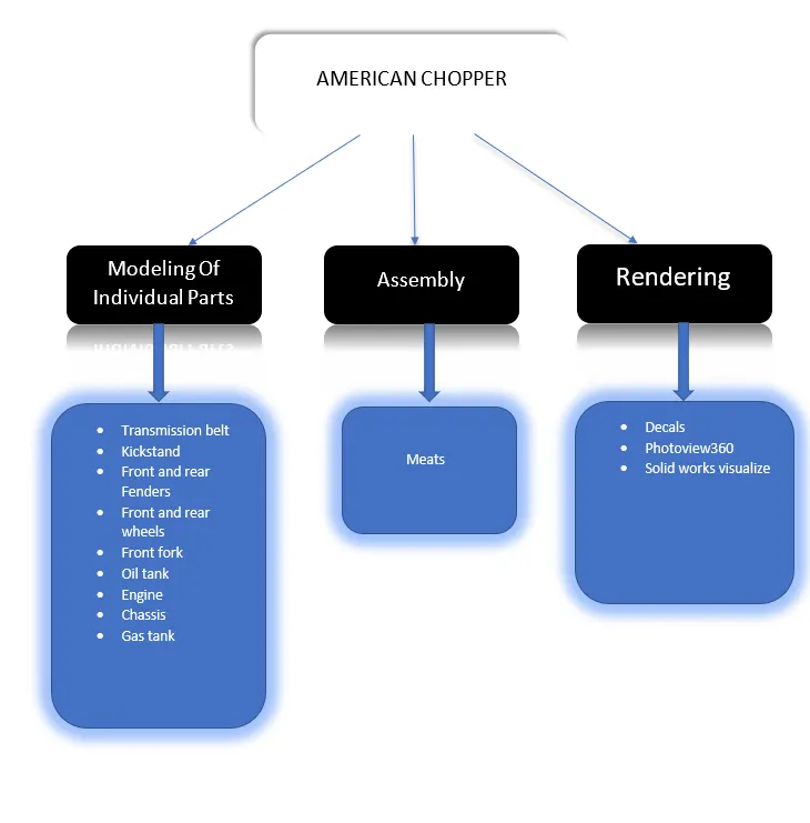
DESCRIPTION:
TRANSMISSION BELT:
Is used to transforn the power from engine to gearbox.
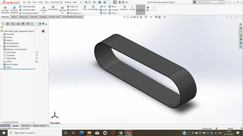
Feture used to create transmission belt:
- sketch
- offset
- Extrude
- Fillet
- appearances
Sketch:-
sketch is a 2D representation of the model.These are known as entities in solidworks,e.g.line,rectangle,circle etc....
Offcet:-
Offset is one or more sketch entities selected models edges or models faces by specified distance. For e.g. you can offset sketch entities such as splines or arcs,set of model edges,loops and so on.You can offcet finite lines,arcs and splines.
Extrude bossbase:-
Creates a 3D solid from an object that encloses an area, or a 3D surface from an object with open ends. Find. Objects can be extruded orthogonally from the plane of the source object, in a specified direction, or along a selected path. You can also specify a taper angle.
Fillet:-
In mechanical engineering, a fillet is a rounding of an interior or exterior corner or edge of a part design. Fillet geometry, when on an exterior corner/edge is of concave function,whereas a fillet on an interior corner is convex.in these cases, fillets are typically referred to as rounds.
Appearances
appearance is the visual properties of a model, including color and texture,it's do not affect physical properties, which are defined by materials.
POCEDURE TO CREATE A MODEL OF TRANSMISSION BELT:
- Firstly,open a new solidworks part file.
- select the plam and sketch the 2D sketch.
- The 2D is created in the front plane and dimensions and relations are given to make the sketch fully defined.Then sketching offset to create the duplicate sketch to some distance.
- After creation the offcet then closed the sketch ans start the extrude by using extrude command is used to convert 2D to 3D model.
- after extrude the skect, then fillet the sketch as per the dimenssion.
- after fillet to give the appearances to part.
- lastly save the part by tha name of transmission belt.
KICKSTAND:
It is also called side stand.it Is used to support the chopper while it needs to rest on the ground.
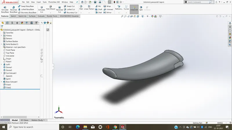
FETURE USED TO CREATE KICKSTAND:
- sketch
- loft
- dome
- extrude boss/base
- extrude cut
- fillet
- split
- Appearances
Sketch:-
sketch is a 2D representation of the model.These are known as entities in solidworks,e.g.line,rectangle,circle etc....
Loft:-
Loft is a variant of a wireframe volume of the 3D object, a technique used in 3D modeling packages.It's developed from planar sections spaced along an approximate path.
Dome:-
Dome is a curved formation or structure. It is shaped like half of a sphere.This is the shape of a dome, although most domes in nature are not perfectly rounded.
Extrude boss/base:-
Extrude boss/base feature will project a 3D model with the selected sketch. Using the 2D sketch plane to create a 3D model.
Extrude cut:-
Extruded cut feature removes material from the part. The End Condition, Draft, and Thin Feature options are same as described in extruded boss/base and You can cut in both directions and mainly used for creating holes,channels,slots etc.....
Fillrt:-
In mechanical engineering, a fillet is a rounding of an interior or exterior corner or edge of a part design. Fillet geometry, when on an exterior corner/edge is of concave function,whereas a fillet on an interior corner is convex.in these cases, fillets are typically referred to as rounds.
Split:-
Split feature is to create multiple parts from an existing part. You can create separate part files, and You can split one or more solid or surface bodies. To split a surface, the Trimming Surface must extend past the boundaries of the surface to split,and you can split faces on multi bodies with one command.
Appearances
appearance is the visual properties of a model, including color and texture,it's do not affect physical properties, which are defined by materials.
FRONT FENDER:
Front fender is mounted on the front fork above the front wheel to protuct the rider and chopper other parts from the debris and puddle.
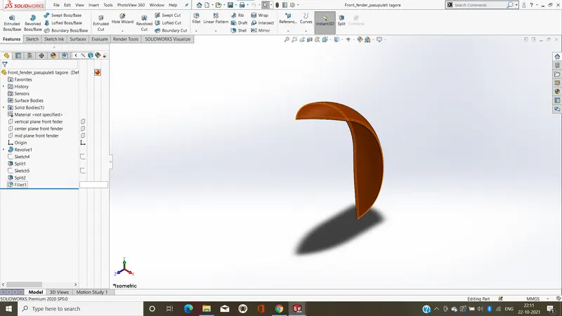
FETURES USED TO CREATE FRONT FENDER:
- sketch
- offset enitities
- trim enitites
- revolve
- dynamic mirror
- split
- appearances
Sketch:-
sketch is a 2D representation of the model.These are known as entities in solidworks,e.g.line,rectangle,circle etc....
Offcet enitities:-
Offset is one or more sketch entities selected models edges or models faces by specified distance. For e.g. you can offset sketch entities such as splines or arcs,set of model edges,loops and so on.You can offcet finite lines,arcs and splines.
Trim enitities:-
Trim command used to remove the objects, which meet the edges of other objects. It is used to remove extra lines or extra parts of an object.
Revolve:-
Revolve have a 2D base shape but instead of extruding it, it is revolved around a specified axis and with a given angle.
Dynamic mirror:-
The Mirror command creates a reverse copy of an object. After you select some objects, and it prompts to select the plane about which the objects will be mirrored.
Split:-
Split feature is to create multiple parts from an existing part. You can create separate part files, and You can split one or more solid or surface bodies. To split a surface, the Trimming Surface must extend past the boundaries of the surface to split,and you can split faces on multi bodies with one command.
Appearances
appearance is the visual properties of a model, including color and texture,it's do not affect physical properties, which are defined by materials.
FRONT WHEEL:
wheel is a circular block made of steel/alloy material.On the top of wheel,the covered.The tire made of rubber.
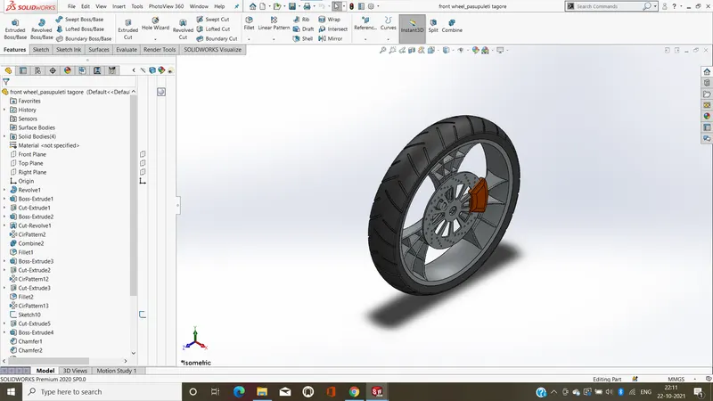
FUTURES USED TO CREATE FRONT WHEEL:
- Sketch
- revolve
- trim
- fillet sketch
- boss extrude
- revolve cut
- chamfer
- cut extrude
- circular pattern
- appearances
Sketch:-
sketch is a 2D representation of the model.These are known as entities in solidworks,e.g.line,rectangle,circle etc....
Revolve:-
Revolve have a 2D base shape but instead of extruding it, it is revolved around a specified axis and with a given angle.
Trim:-
Trim command used to remove the objects, which meet the edges of other objects. It is used to remove extra lines or extra parts of an object.
Fillrt sketch :-
In mechanical engineering, a fillet is a rounding of an interior or exterior corner or edge of a part design. Fillet geometry, when on an exterior corner/edge is of concave function,whereas a fillet on an interior corner is convex.in these cases, fillets are typically referred to as rounds.
Boss extrude:-
Boss extrude feature will project a 3D model with the selected sketch. Using the 2D sketch plane to create a 3D model.
Revolve cut:-
Revolved cut feature is one of the very useful solidworks feature tool, which helps to remove materials from 3D models possess axis symmetry, and it removes materials by revolving a closed profile along an axis.
Chamfer:-
chamfer tool creates a beveled feature on selected edges, faces, or a vertex.
Cut extrude:-
Extruded cut feature removes material from the part. The End Condition, Draft, and Thin Feature options are same as described in extruded boss/base and You can cut in both directions and mainly used for creating holes,channels,slots etc.....
Circular pattern:-
circular patterns to create multiple instances of one or more features that you can space uniformly around an axis.
Appearances
appearance is the visual properties of a model, including color and texture,it's do not affect physical properties, which are defined by materials.
REAR FENDER:
Rear fender uses is the same as the front femder,and it will place on the chasis of the rear part above the rear wheel.
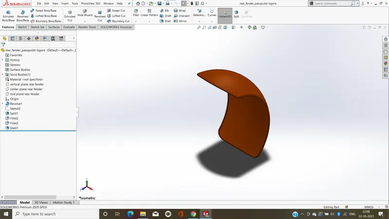
FUTURES USE TO CREATE THE REAR FENDER:
- sketch
- offset entities
- trim entities
- revolve
- split
- fillet
- appearances
Sketch:-
sketch is a 2D representation of the model.These are known as entities in solidworks,e.g.line,rectangle,circle etc....
Offcet enitities:-
Offset is one or more sketch entities selected models edges or models faces by specified distance. For e.g. you can offset sketch entities such as splines or arcs,set of model edges,loops and so on.You can offcet finite lines,arcs and splines.
Trim enitities:-
Trim command used to remove the objects, which meet the edges of other objects. It is used to remove extra lines or extra parts of an object.
Revolve:-
Revolve have a 2D base shape but instead of extruding it, it is revolved around a specified axis and with a given angle.
Split:-
Split feature is to create multiple parts from an existing part. You can create separate part files, and You can split one or more solid or surface bodies. To split a surface, the Trimming Surface must extend past the boundaries of the surface to split,and you can split faces on multi bodies with one command.
Appearances
appearance is the visual properties of a model, including color and texture,it's do not affect physical properties, which are defined by materials.
REAR WHEEL:
Rear wheel is a circular object that revolves on an axis and is fixed end of the chasis, it used to move easily over the ground.
the disk and sprocket are attach the rear wheel.
the chain is connectded from engine to rear wheel.
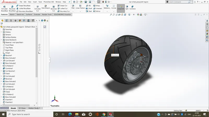
FETURE USED TO CREATE REAR WHEEL:
- Sketch
- revolve
- trim
- fillet sketch
- boss extrude
- revolve cut
- chamfer
- cut extrude
- circular pattern
- appearances
Sketch:-
sketch is a 2D representation of the model.These are known as entities in solidworks,e.g.line,rectangle,circle etc....
Revolve:-
Revolve have a 2D base shape but instead of extruding it, it is revolved around a specified axis and with a given angle.
Trim:-
Trim command used to remove the objects, which meet the edges of other objects. It is used to remove extra lines or extra parts of an object.
Fillet sketch :-
In mechanical engineering, a fillet is a rounding of an interior or exterior corner or edge of a part design. Fillet geometry, when on an exterior corner/edge is of concave function,whereas a fillet on an interior corner is convex.in these cases, fillets are typically referred to as rounds.
Boss extrude:-
Boss extrude feature will project a 3D model with the selected sketch. Using the 2D sketch plane to create a 3D model.
Revolve cut:-
Revolved cut feature is one of the very useful solidworks feature tool, which helps to remove materials from 3D models possess axis symmetry, and it removes materials by revolving a closed profile along an axis.
Chamfer:-
chamfer tool creates a beveled feature on selected edges, faces, or a vertex.
Cut extrude:-
Extruded cut feature removes material from the part. The End Condition, Draft, and Thin Feature options are same as described in extruded boss/base and You can cut in both directions and mainly used for creating holes,channels,slots etc.....
Circular pattern:-
circular patterns to create multiple instances of one or more features that you can space uniformly around an axis.
Appearances
appearance is the visual properties of a model, including color and texture,it's do not affect physical properties, which are defined by materials.
FRONT FORK:
most motorcycle today use the telescopic forks for the front suspension.the fork can be easily understood as simply large hydraulic shock absorbes with internal coil springs. the allow front fork wheel to react to imperfection in the road while isolating the rest of the motorcycle from that motation.
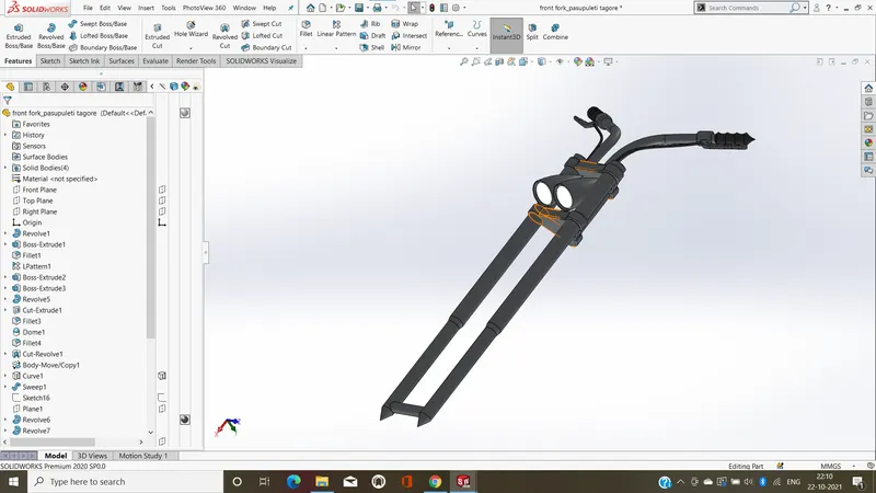
FETURE USED TO CREATE FRONT FORK:
- sketch
- revolve
- revolve cut
- extrude boss/base
- extrude cut
- fillet
- linear pattern
- dome
- split
- move/copy body
- mirror
- combine
- project curve
- sweep
- appearances
Sketch:-
sketch is a 2D representation of the model.These are known as entities in solidworks,e.g.line,rectangle,circle etc....
Revolve:-
Revolve have a 2D base shape but instead of extruding it, it is revolved around a specified axis and with a given angle.
Revolve cut:-
Revolved cut feature is one of the very useful solidworks feature tool, which helps to remove materials from 3D models possess axis symmetry, and it removes materials by revolving a closed profile along an axis.
Boss extrude:-
Boss extrude feature will project a 3D model with the selected sketch. Using the 2D sketch plane to create a 3D model.
Cut extrude:-
Extruded cut feature removes material from the part. The End Condition, Draft, and Thin Feature options are same as described in extruded boss/base and You can cut in both directions and mainly used for creating holes,channels,slots etc.....
Fillet:-
In mechanical engineering, a fillet is a rounding of an interior or exterior corner or edge of a part design. Fillet geometry, when on an exterior corner/edge is of concave function,whereas a fillet on an interior corner is convex.in these cases, fillets are typically referred to as rounds.
linear pattern:-
linear patterns to create multiple instances of one or more features that you can space uniformly along one or two linear paths.
Dome:-
Dome is a curved formation or structure. It is shaped like half of a sphere.This is the shape of a dome, although most domes in nature are not perfectly rounded.
Split:-
Split feature is to create multiple parts from an existing part. You can create separate part files, and You can split one or more solid or surface bodies. To split a surface, the Trimming Surface must extend past the boundaries of the surface to split,and you can split faces on multi bodies with one command.
Move/copy body
In multibody parts, you can move , rotate, and copy solid and surface bodies, or place them using mates.
Mirror:-
Mirror tool to copy features and geometry about a planar surface. The mirrored copy can be independent, or dependent so it updates with the original feature or geometry.
Combined:-
combined allows to add two bodies together, and keep the area that is common to them. To use this feature, will select the common button, and then under Bodies to Combine, select the two bodiesprojected curve
project curve:-
to project a sketched curve onto a model face to create a 3D curve, that represents the intersection of two extruded surfaces generated by creating sketches on two intersecting plane.
Sweep:-
sweep is a tool that creates a solid, a cut or a surface feature by moving a profile along a path.
Appearances
appearance is the visual properties of a model, including color and texture,it's do not affect physical properties, which are defined by materials.
PEDAL:
it is the externally attached to the chasis,and it is used to place the leg on top of that to give comfort to rider.
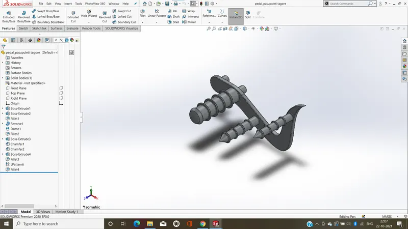
FETURE USED TO CREATE PEDAL:
- sketch
- fillet
- boss extrude
- chamfer
- linear pattern
- dome
- revolve
- appearances
Sketch:-
sketch is a 2D representation of the model.These are known as entities in solidworks,e.g.line,rectangle,circle etc....
Fillet:-
In mechanical engineering, a fillet is a rounding of an interior or exterior corner or edge of a part design. Fillet geometry, when on an exterior corner/edge is of concave function,whereas a fillet on an interior corner is convex.in these cases, fillets are typically referred to as rounds.
Boss extrude:-
Boss extrude feature will project a 3D model with the selected sketch. Using the 2D sketch plane to create a 3D model.
Chamfer:-
chamfer tool creates a beveled feature on selected edges, faces, or a vertex.
linear pattern:-
linear patterns to create multiple instances of one or more features that you can space uniformly along one or two linear paths.
Dome:-
Dome is a curved formation or structure. It is shaped like half of a sphere.This is the shape of a dome, although most domes in nature are not perfectly rounded.
Revolve:-
Revolve have a 2D base shape but instead of extruding it, it is revolved around a specified axis and with a given angle.
Appearances
appearance is the visual properties of a model, including color and texture,it's do not affect physical properties, which are defined by materials.
CHAIN:
chain is a serial assembly of connected pieces, called links, typically made of metal, with an overall character similar to that of a rope in that it is flexible and curved incompressio but liner,rigid,and load-bearing in tension.A chain may consist of two or more links.and chain is a type of transmission system that is used to transform power from engine to rear wheel,is connected with sprocket by using shoft and key.
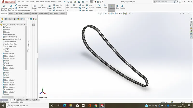
FETURES USED TO CREATE CHAIN:
- sketch
- boss extrude
- fillet
- blocks
- curve driven pattern
- mirror
- appearances
Sketch:-
sketch is a 2D representation of the model.These are known as entities in solidworks,e.g.line,rectangle,circle etc....
Boss extrude:-
Boss extrude feature will project a 3D model with the selected sketch. Using the 2D sketch plane to create a 3D model.
Fillet:-
In mechanical engineering, a fillet is a rounding of an interior or exterior corner or edge of a part design. Fillet geometry, when on an exterior corner/edge is of concave function,whereas a fillet on an interior corner is convex.in these cases, fillets are typically referred to as rounds.
Blocks:-
to make block:
- first create a sketch.
- make a block by using make block command.
- select the entity you want to make as a block for block entity.
- click ok to save the block.
- repat 2and4 steps for creationg second block.
- in sketch edit mode,and necessary relations.
- lastly save the model.
Curve driven pattern:-
Curve Driven Pattern tool allows you to create patterns along a planar or 3D curve and you can use any sketch segment, or the edge of a solid or surface face,that lies along the plane.
Mirror:-
Mirror tool to copy features and geometry about a planar surface. The mirrored copy can be independent, or dependent so it updates with the original feature or geometry.
A
Appearances
appearance is the visual properties of a model, including color and texture,it's do not affect physical properties, which are defined by materials.
CHASIS:
chassis or frame forms its skeleton. All the components of a motorcycle, like the suspension, wheels, fuel tank, seats, handlebars etc, are attached to this base structure which lends a motorcycle its strength and ability to handle well.
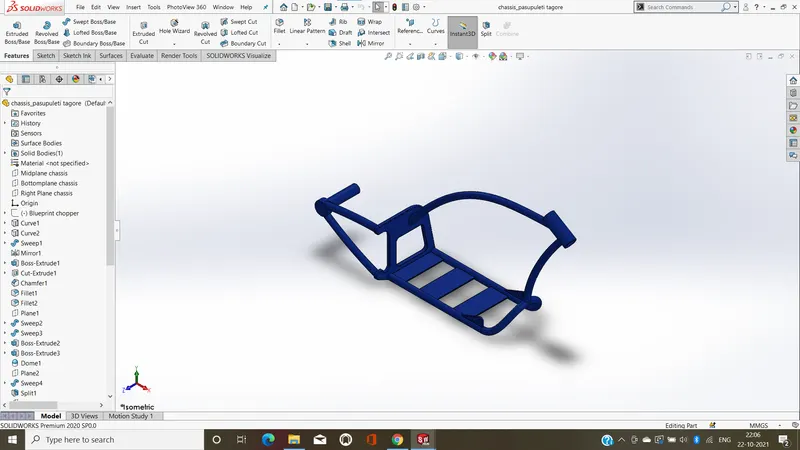
FETURES USED TO CREATE CHASSIS:
- sketch
- project curve
- sweep
- convert entitites
- mirror
- boss extrude
- extrude cut
- revolve
- dome
- chamfer
- fillet
- split
- combined
- appearances
Sketch:-
sketch is a 2D representation of the model.These are known as entities in solidworks,e.g.line,rectangle,circle etc....
project curve:-
to project a sketched curve onto a model face to create a 3D curve, that represents the intersection of two extruded surfaces generated by creating sketches on two intersecting plane.
Sweep:-
sweep is a tool that creates a solid, a cut or a surface feature by moving a profile along a path.
Convert entities:-
Convert Entities tool allows users to make a copied projection of a given sketch, face, or set of edges onto the active sketch plane.
Mirror:-
Mirror tool to copy features and geometry about a planar surface. The mirrored copy can be independent, or dependent so it updates with the original feature or geometry.
Boss extrude:-
Boss extrude feature will project a 3D model with the selected sketch. Using the 2D sketch plane to create a 3D model.
Cut extrude:-
Extruded cut feature removes material from the part. The End Condition, Draft, and Thin Feature options are same as described in extruded boss/base and You can cut in both directions and mainly used for creating holes,channels,slots etc.....
Revolve:-
Revolve have a 2D base shape but instead of extruding it, it is revolved around a specified axis and with a given angle.
Dome:-
Dome is a curved formation or structure. It is shaped like half of a sphere.This is the shape of a dome, although most domes in nature are not perfectly rounded.
Chamfer:-
chamfer tool creates a beveled feature on selected edges, faces, or a vertex.
Fillet:-
In mechanical engineering, a fillet is a rounding of an interior or exterior corner or edge of a part design. Fillet geometry, when on an exterior corner/edge is of concave function,whereas a fillet on an interior corner is convex.in these cases, fillets are typically referred to as rounds.
Split:-
Split feature is to create multiple parts from an existing part. You can create separate part files, and You can split one or more solid or surface bodies. To split a surface, the Trimming Surface must extend past the boundaries of the surface to split,and you can split faces on multi bodies with one command.
Combined:-
combined allows to add two bodies together, and keep the area that is common to them. To use this feature, will select the common button, and then under Bodies to Combine, select the two bodiesprojected curve
Appearances
appearance is the visual properties of a model, including color and texture,it's do not affect physical properties, which are defined by materials.
ENGINE:
An engine is some machine that converts energy from a fuel to some mechanical energy, creating motion in the process. such as the ones used to run vehicles,can run on a variety of different fuels, most notably gasoline and diesel.
engine is a primary mover for bike,it converts chemical energey to heat energey and than heat energey convert to mechanical work,is a rotational motation,this motation is transmited with the help of clutch and gear box.
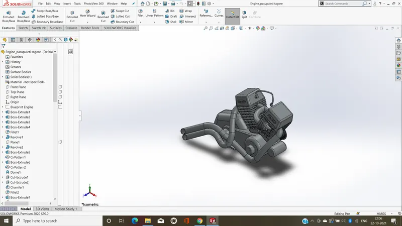
FETURE USED FOR CREATING ENGINE:
- sketch
- boss extrude
- fillet
- revolve
- circular pattern
- dome
- cut extrude
- chamfer
- linear pattern
- mirror
- sweep
- composite curve
- project curve
- split
- combined
- appearances
Sketch:-
sketch is a 2D representation of the model.These are known as entities in solidworks,e.g.line,rectangle,circle etc....
Boss extrude:-
Boss extrude feature will project a 3D model with the selected sketch. Using the 2D sketch plane to create a 3D model.
Fillet:-
In mechanical engineering, a fillet is a rounding of an interior or exterior corner or edge of a part design. Fillet geometry, when on an exterior corner/edge is of concave function,whereas a fillet on an interior corner is convex.in these cases, fillets are typically referred to as rounds.
Revolve:-
Revolve have a 2D base shape but instead of extruding it, it is revolved around a specified axis and with a given angle.
Circular pattern:-
circular patterns to create multiple instances of one or more features that you can space uniformly around an axis.
Dome:-
Dome is a curved formation or structure. It is shaped like half of a sphere.This is the shape of a dome, although most domes in nature are not perfectly rounded.
Cut extrude:-
Extruded cut feature removes material from the part. The End Condition, Draft, and Thin Feature options are same as described in extruded boss/base and You can cut in both directions and mainly used for creating holes,channels,slots etc.....
Chamfer:-
chamfer tool creates a beveled feature on selected edges, faces, or a vertex.
linear pattern:-
linear patterns to create multiple instances of one or more features that you can space uniformly along one or two linear paths.
Mirror:-
Mirror tool to copy features and geometry about a planar surface. The mirrored copy can be independent, or dependent so it updates with the original feature or geometry.
Sweep:-
sweep is a tool that creates a solid, a cut or a surface feature by moving a profile along a path.
Composite curve;-
composite curves created by combining curves, sketch geometry, and model edges into a single curve.
project curve:-
to project a sketched curve onto a model face to create a 3D curve, that represents the intersection of two extruded surfaces generated by creating sketches on two intersecting plane.
Split:-
Split feature is to create multiple parts from an existing part. You can create separate part files, and You can split one or more solid or surface bodies. To split a surface, the Trimming Surface must extend past the boundaries of the surface to split,and you can split faces on multi bodies with one command.
Combined:-
combined allows to add two bodies together, and keep the area that is common to them. To use this feature, will select the common button, and then under Bodies to Combine, select the two bodiesprojected curve.
Appearances
appearance is the visual properties of a model, including color and texture,it's do not affect physical properties, which are defined by materials.
OIL TANK :
oil tnak is used to store the oil required to run the engine.it is hollow,tha thickness is given by 3mm in our chopper model.
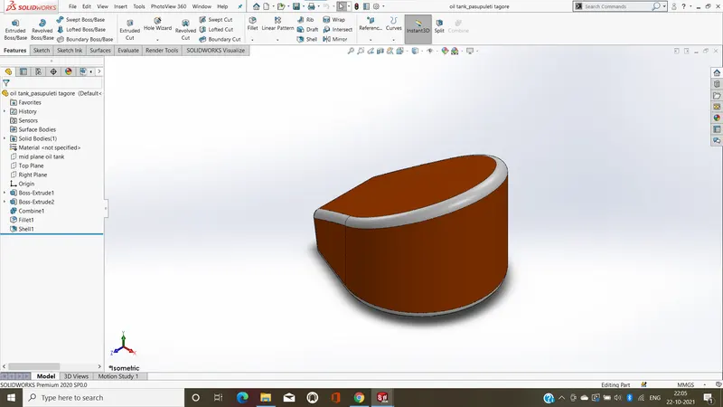
FETURES USED TO CREATE OILTANK:
- sketch
- boss extrude
- combined
- fillet
- shell
- appearances
Sketch:-
sketch is a 2D representation of the model.These are known as entities in solidworks,e.g.line,rectangle,circle etc....
Boss extrude:-
Boss extrude feature will project a 3D model with the selected sketch. Using the 2D sketch plane to create a 3D model.
Combined:-
combined allows to add two bodies together, and keep the area that is common to them. To use this feature, will select the common button, and then under Bodies to Combine, select the two bodiesprojected curve.
Fillet:-
In mechanical engineering, a fillet is a rounding of an interior or exterior corner or edge of a part design. Fillet geometry, when on an exterior corner/edge is of concave function,whereas a fillet on an interior corner is convex.in these cases, fillets are typically referred to as rounds.
Shell:-
The shell tool hollows out a part, leaves open the faces you select, and creates thin-walled features on the remaining faces or do not select any face on the model, you can shell a solid part, creating a closed, hollow model.
Appearances
appearance is the visual properties of a model, including color and texture,it's do not affect physical properties, which are defined by materials.
GAS TANK:
gas tank are used to store gas and its gives gas to the engine when it requireds.
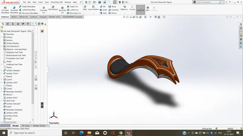
FETURES TO CREATE THE GAS TANK:
- sketch
- surface trim
- surface loft
- boundary surface
- mirror
- surface kint
- surface extrude
- fillet
- sweep cut
- shell
- appearances
Sketch:-
sketch is a 2D representation of the model.These are known as entities in solidworks,e.g.line,rectangle,circle etc....
Surface trim:-
Create two or more surfaces that intersect at one or more points, or create a surface that intersects with a plane or has a sketch on its face.
Surface loft:-
Create a plane for each profile section of the loft. Sketch the section profiles on the planes, can create all section and guide curve sketches inside a single 3D sketch.
Boundarey surface:-
boundary surface feature lets you create surfaces that can be tangent or curvature continuous in both directions.
Mirror:-
Mirror tool to copy features and geometry about a planar surface. The mirrored copy can be independent, or dependent so it updates with the original feature or geometry.
Surface kint:-
Knit Surface tool to combine two or more faces and surfaces into one.
Surface extrude:-
Is create extruded surfaces from models that include 2D or 3D faces and knit the extruded surfaces to surrounding features.
Fillet:-
In mechanical engineering, a fillet is a rounding of an interior or exterior corner or edge of a part design. Fillet geometry, when on an exterior corner/edge is of concave function,whereas a fillet on an interior corner is convex.in these cases, fillets are typically referred to as rounds.
Sweep cut:-
is used to cut a solid model or part by sweeping a completely closed profile along an open or closed path.
Shell:-
The shell tool hollows out a part, leaves open the faces you select, and creates thin-walled features on the remaining faces or do not select any face on the model, you can shell a solid part, creating a closed, hollow model.
Appearances
appearance is the visual properties of a model, including color and texture,it's do not affect physical properties, which are defined by materials.
ASSEMBLY OF THE CHOPPER:
- initially insert the chassis part in assembly by using insert part option,after insert tha chassis in assembly environment than click ok to fix the chassis.
- after fix the chassis, to insert the other parts of copper into assembly environment and given possible meat conditions.
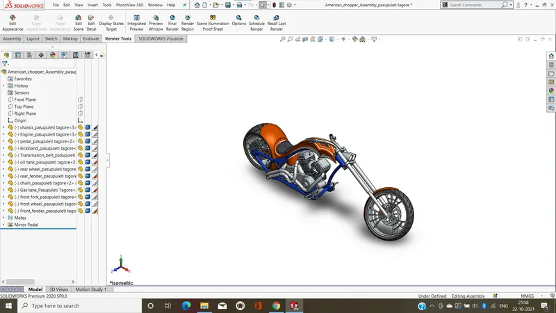
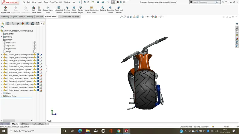
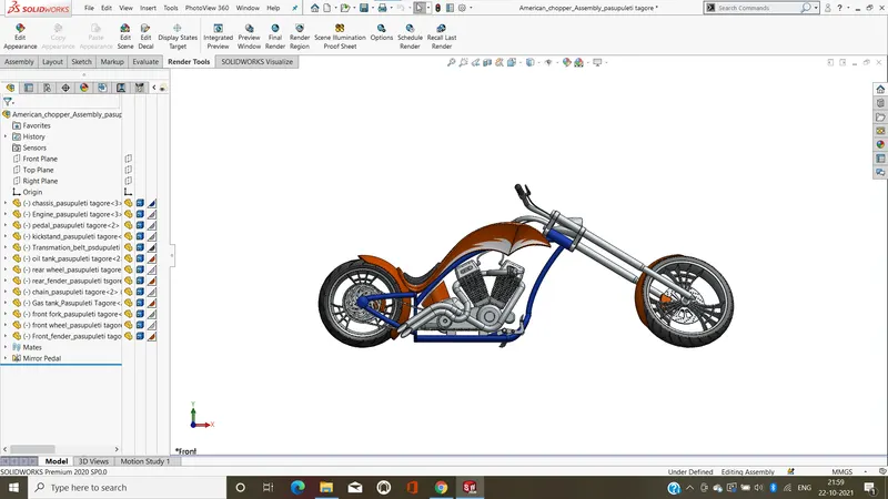
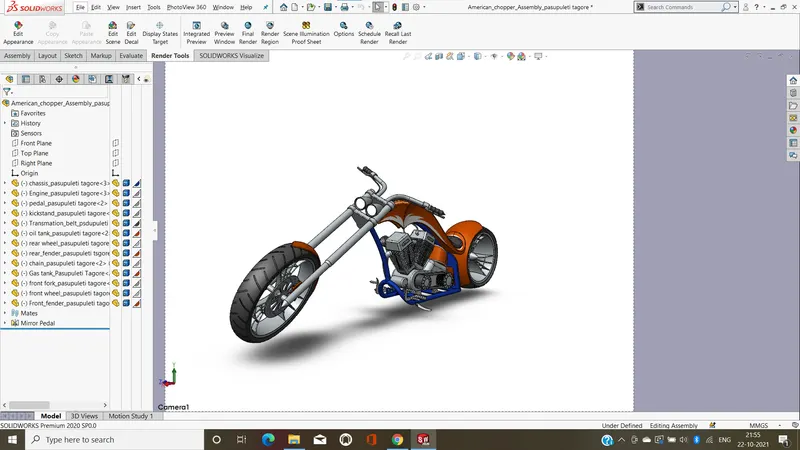
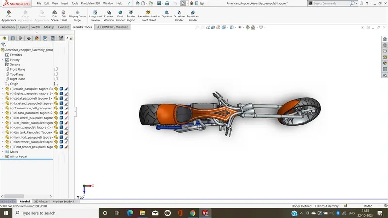
FETURES USED TO ASSEMBLY CHOPPER:
- insert parts
- mates
Mates:-
select the entities that you want to mate together for Entities to Mate . You can temporarily hide faces to select an obscured face by hovering over a face and pressing Alt.
RENDERING:
- rendering is a processe of creationga realistic images.
- rendering done by 2 ways.
- photoview 360
- solidworks visualize
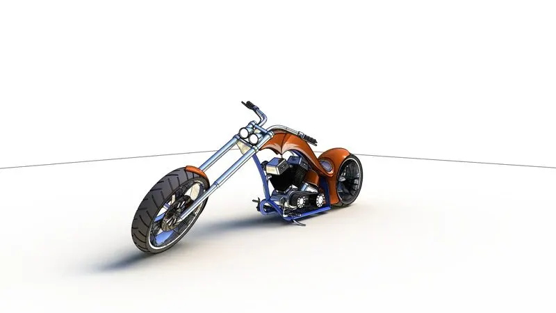
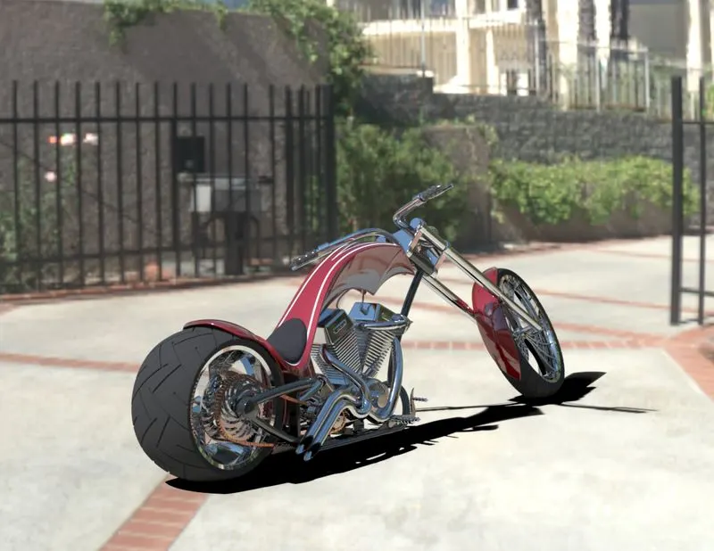
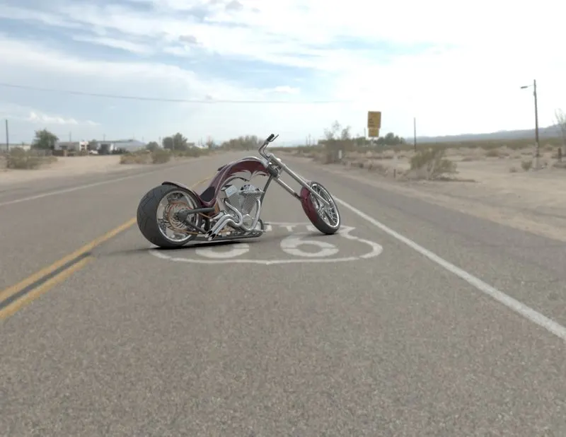
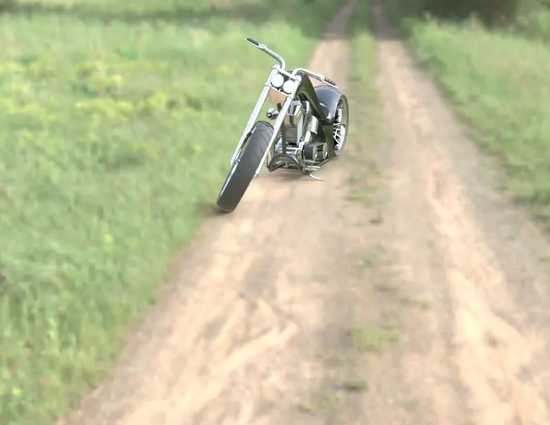
the photorealistic model is rendered into realistic images with different views
PHOTOVIEW360:
PhotoView 360 is a visualization and rendering solution.and it's Providing a highly interactive environment for viewing designs as well as for creating photo-realistic renderings that can be used to showcase our design.
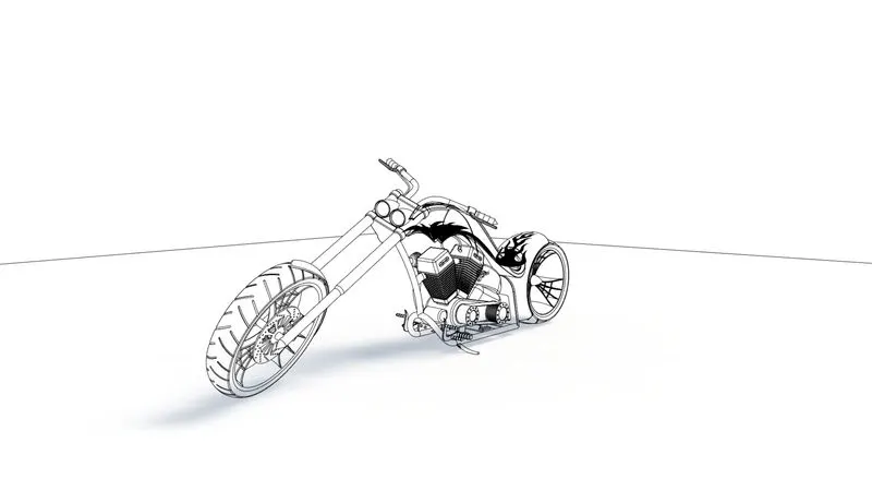
SOLID WORK VISUALIZE:
Solidwork Visualize allows you to leverage your 3D CAD data to create photo-quality content in the fastest and easiest way,you can from images to animations, interactive web content, and immersive Virtual Reality. Bring your products to life. SOLIDWORKS Visualize is the “camera” for our design.
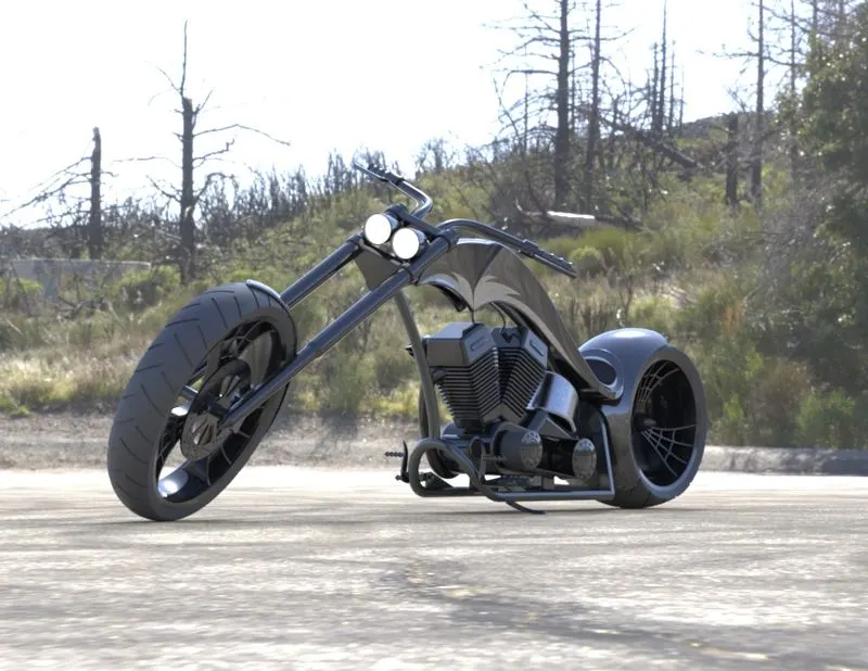
CONCLUSION:
- all part of chopper are modeled,and insert tha assembly enevirnoment and chopper is assembled.
- good knowladge about all futers tools and rendering tools.
- learn how to render image by adding types of material,camera view,and enevirnoment.