Radar Mast & Final Assembly of Yacht
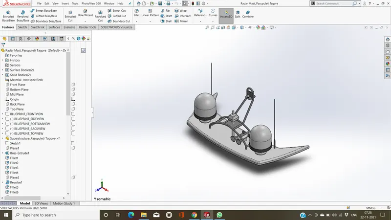
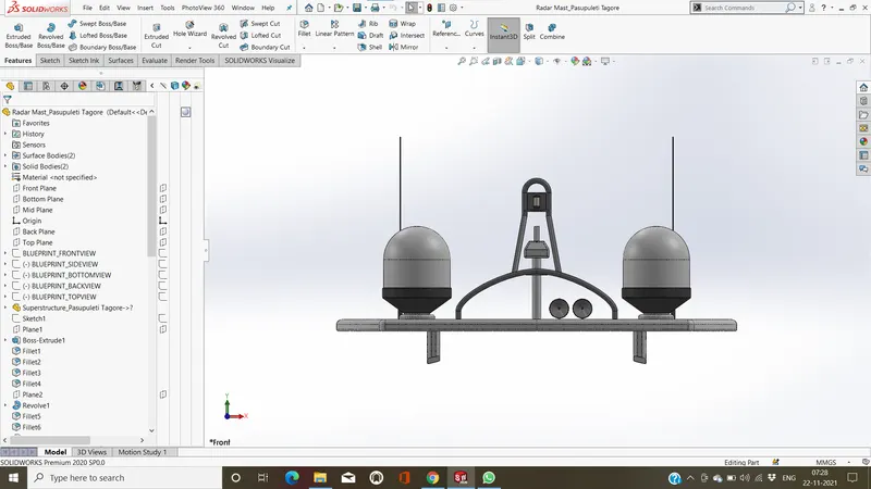
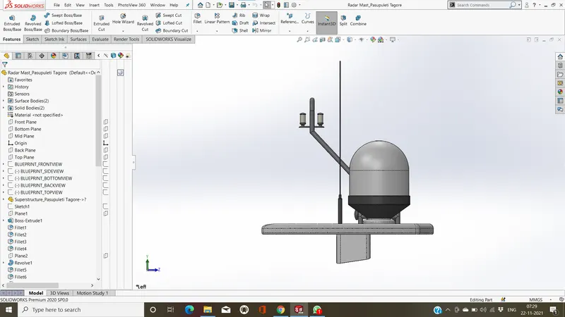
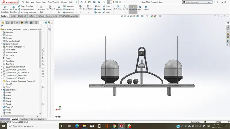
MODELLING SUNSEEKER PREDATOR YACHT IN SOLID WORKS :
OBJECTIVE :
- to create the individual parts of Yacht by using solidworks 2020
- assemble tha all parts of Yacht.
- know the applications of decals,lights,views etc...
- to create the relastic images and renders by using photoview360 and solidworks visualize.
INTRODUCTION :
A yacht is a craft used for pleasure and sport. The name comes from the Dutch word jaght, which translates as ‘hunter’.yacht, a sail- or power-driven vessel, usually light and comparatively small, used for racing or for recreation. In recreation, the term applies to very large craft, originally powered by sail and later by steam or internal-combustion engines.
DESIGN METHODOLOGY : FLOW CHART
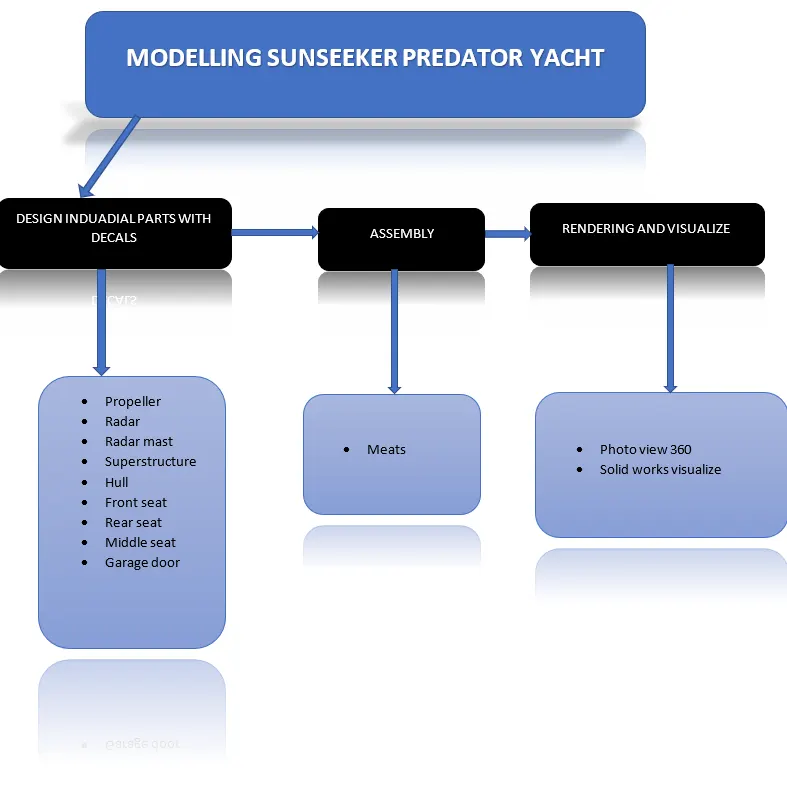
DESCRIPTION:
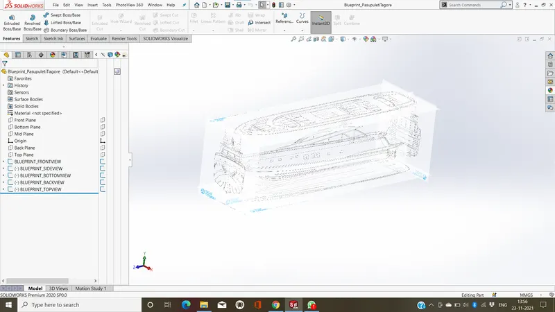
BLUEPRINT :
blueprint as in serving as a model or providing guidance especially a detailed plan or program of action.
PROPELLER :
A propeller is a device with a rotating hub and radiating blades that are set at a pitch to form a helical spiral, that, when rotated, exerts linear thrust upon a working fluid, such as water.
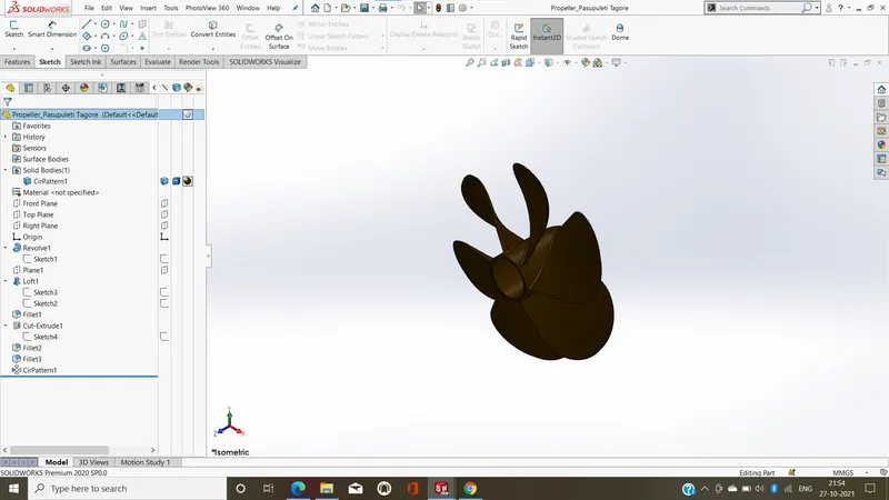
FEATURES USED TO CREATE PROPRLLER :
- Sketch
- Revolve
- Lofted Bose/Base
- Cut Extrude
- Fillet
- Circular Pattern
- Apperances
sketch:
sketch is a 2D representation of the model.These are known as entities in solidworks,e.g.line,rectangle,circle etc....
Revolve :
Revolve have a 2D base shape but instead of extruding it, it is revolved around a specified axis and with a given angle.
Lofted Bose/Base:
Loft creates a feature by making transitions between profiles. A loft can be a base, boss, cut, or surface. You create a loft using two or more profiles. Only the first, last, or first and last profiles can be points.
Cut Extrude :
Extruded cut feature removes material from the part. The End Condition, Draft, and Thin Feature options are same as described in extruded boss/base and You can cut in both directions and mainly used for creating holes,channels,slots etc.....
Fillet :
In mechanical engineering, a fillet is a rounding of an interior or exterior corner or edge of a part design. Fillet geometry, when on an exterior corner/edge is of concave function,whereas a fillet on an interior corner is convex.in these cases, fillets are typically referred to as rounds.
Circular Pattern :
circular patterns to create multiple instances of one or more features that you can space uniformly around an axis.
Appearances :
appearance is the visual properties of a model, including color and texture,it's do not affect physical properties, which are defined by materials.
Super Structure :
superstructure consists of the parts of the ship or a boat,that project above her main deck.
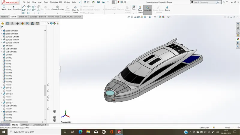
FEATURE USED TO CREATE SUPERSTRUCTURE :
- Sketch
- Blueprint
- Isert Part
- Surface Extrude
- Swept Surface
- Surface kint
- Ruled Surface
- Surface Trim
- Fillet
- Reference Plane
- Projrctive Curve
- Surface Fill
- Lofted Surface
- 3D Sketch
- Surface Extend
- Delete Face
- Boss Extrude
- Cut Extrude
- surface offcet
- thicken
- Dome
- Sweep
- Thine Cut Extrude
- Split line
- Mirror
- Chamfer
- Appearances
- decals
sketch:
sketch is a 2D representation of the model.These are known as entities in solidworks,e.g.line,rectangle,circle etc....
Blueprint:
blueprint as in serving as a model or providing guidance especially a detailed plan or program of action.
Isert Part :
Under Transfer, select any combination of items from the inserted part to be included in the derived part.
Surface Extrude :
extrude the boundary edges of a face of a solid body or edges of a surface body in a customized direction.
Swept Surface :
Create planes for sketching the sweep profile, sweep path, and if necessary, the guide curves.
Surface Kint :
Knit Surface tool to combine two or more faces and surfaces into one.
Ruled Surface :
surfaces that are generated using two curves with a straight line connecting each curve.
Surface Trim :
It's a handy tool to cut away, trim or sketch geometry quickly.
Fillet :
In mechanical engineering, a fillet is a rounding of an interior or exterior corner or edge of a part design. Fillet geometry, when on an exterior corner/edge is of concave function,whereas a fillet on an interior corner is convex.in these cases, fillets are typically referred to as rounds.
Reference Planes:
the reference plane is the plane used to define orbital positions.
Projective curves :
to project a sketched curve onto a model face to create a 3D curve, that represents the intersection of two extruded surfaces generated by creating sketches on two intersecting plane.
Surface Fill :
It constructs a surface patch with any number of sides, within a boundary defined by existing model edges, sketches, or curves, including composite curves. You can use this feature to construct a surface to fill a gap in a model.
Lofted Surface :
surfaces generated by multiple 3D Curves or existing edges creating a smooth tangency between the selected curves.
3D Sketch :
A 3D sketch plane is a 2D plane that only exists inside the 3D sketch.When activated, sketching will happen exclusively on that plane and you will get behavior similar to when working in a 2D sketch.
Surface Extend :
the surface extends along all edges of the face except those connected to another face.
Delete Face :
Easily Remove Faces From a Solid or Surface Body.
Boss Extrude :
Boss extrude feature will project a 3D model with the selected sketch. Using the 2D sketch plane to create a 3D model.
Cut Extrude :
Extruded cut feature removes material from the part. The End Condition, Draft, and Thin Feature options are same as described in extruded boss/base and You can cut in both directions and mainly used for creating holes,channels,slots etc.....
Surface Offset
faces that can't be offset the desired amount are automatically identified and highlighted in the tree.
Thicken :
If the surface you want to thicken is comprised of multiple adjacent surfaces, you must first knit the surfaces together before you thicken the surface.
Dome :
Dome is a curved formation or structure. It is shaped like half of a sphere.This is the shape of a dome, although most domes in nature are not perfectly rounded.
Sweep :
sweep is a tool that creates a solid, a cut or a surface feature by moving a profile along a path.
Thin Extrude :
the sketched profile and creates a constant thickness in the sketch plane
Split line :
2 to separate or be separated from a whole Part.
Mirror :
Mirror tool to copy features and geometry about a planar surface. The mirrored copy can be independent, or dependent so it updates with the original feature or geometry.
Chamfer :
chamfer tool creates a beveled feature on selected edges, faces, or a vertex.
Appearances :
appearance is the visual properties of a model, including color and texture,it's do not affect physical properties, which are defined by materials.
Decals :
A decal is a 2D image applied to a model and it can used to create model details that you can represent with an image instead of with the model geometry, such as a car grill or a picture frame.
REAR SEAT :
that is equipped with a restraining device or harness and can be fastened to the seating.
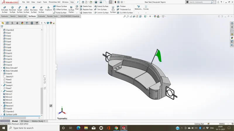
FEATURES USED TO CREATE REAR SEAT :
- Sketch
- Blueprint
- Isert Part
- 3D Sketch
- Swept Surface
- Surface Offset
- Surface Trim
- Surface Extend
- Surface kint
- Surface Extrude
- Surface Loft
- Boss Extrude
- Cut Extrude
- Chamfer
- Surfce Offset
- Fillet
- Sweep
- Mirror
- Revolve
sketch:
sketch is a 2D representation of the model.These are known as entities in solidworks,e.g.line,rectangle,circle etc....
Blueprint:
blueprint as in serving as a model or providing guidance especially a detailed plan or program of action.
Isert Part :
Under Transfer, select any combination of items from the inserted part to be included in the derived part.
3D Sketch :
A 3D sketch plane is a 2D plane that only exists inside the 3D sketch.When activated, sketching will happen exclusively on that plane and you will get behavior similar to when working in a 2D sketch.
Swept Surface :
Create planes for sketching the sweep profile, sweep path, and if necessary, the guide curves.
Surface Offset
faces that can't be offset the desired amount are automatically identified and highlighted in the tree.
Surface Trim :
It's a handy tool to cut away, trim or sketch geometry quickly.
Surface Extend :
the surface extends along all edges of the face except those connected to another face.
Surface Kint :
Knit Surface tool to combine two or more faces and surfaces into one.
Surface Extrude :
extrude the boundary edges of a face of a solid body or edges of a surface body in a customized direction.
Lofted Surface :
surfaces generated by multiple 3D Curves or existing edges creating a smooth tangency between the selected curves.
Boss Extrude :
Boss extrude feature will project a 3D model with the selected sketch. Using the 2D sketch plane to create a 3D model.
Cut Extrude :
Extruded cut feature removes material from the part. The End Condition, Draft, and Thin Feature options are same as described in extruded boss/base and You can cut in both directions and mainly used for creating holes,channels,slots etc.....
Chamfer :
chamfer tool creates a beveled feature on selected edges, faces, or a vertex.
Fillet :
In mechanical engineering, a fillet is a rounding of an interior or exterior corner or edge of a part design. Fillet geometry, when on an exterior corner/edge is of concave function,whereas a fillet on an interior corner is convex.in these cases, fillets are typically referred to as rounds.
Sweep :
sweep is a tool that creates a solid, a cut or a surface feature by moving a profile along a path.
Mirror :
Mirror tool to copy features and geometry about a planar surface. The mirrored copy can be independent, or dependent so it updates with the original feature or geometry.
Revolve :
Revolve have a 2D base shape but instead of extruding it, it is revolved around a specified axis and with a given angle.
Appearances :
appearance is the visual properties of a model, including color and texture,it's do not affect physical properties, which are defined by materials.
RADAR :
used to detect other ships and land obstacles, to provide bearing and distance for collision avoidance and navigation at sea.
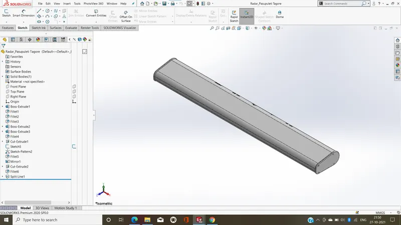
FEATURES USED TO CREATE RADAR :
- Sketch
- Boss Extrude
- Sketch text
- Fillet
- Cut Extrude
- Sketch Driven Pattern
- Mirror
- Split Line
- Appearances
sketch:
sketch is a 2D representation of the model.These are known as entities in solidworks,e.g.line,rectangle,circle etc....
Boss Extrude :
Boss extrude feature will project a 3D model with the selected sketch. Using the 2D sketch plane to create a 3D model.
Sketch Text :
The text is sketched along the outside edge of the face of the part, formatted, then cut.
Fillet :
In mechanical engineering, a fillet is a rounding of an interior or exterior corner or edge of a part design. Fillet geometry, when on an exterior corner/edge is of concave function,whereas a fillet on an interior corner is convex.in these cases, fillets are typically referred to as rounds.
Cut Extrude :
Extruded cut feature removes material from the part. The End Condition, Draft, and Thin Feature options are same as described in extruded boss/base and You can cut in both directions and mainly used for creating holes,channels,slots etc.....
Sketch Driven Pattern :
Open a sketch on the face of a part to create a seed feature on the model. use sketch driven patterns for holes or other feature instances.
Mirror :
Mirror tool to copy features and geometry about a planar surface. The mirrored copy can be independent, or dependent so it updates with the original feature or geometry.
Split line :
2 to separate or be separated from a whole Part.
Appearances :
appearance is the visual properties of a model, including color and texture,it's do not affect physical properties, which are defined by materials.
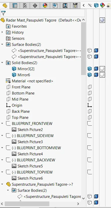
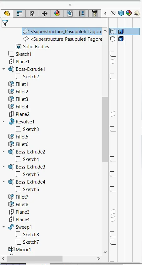
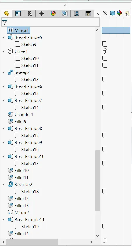
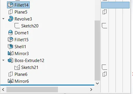
RADAR MAST :
used to detect other ships and land obstacles, to provide bearing and distance for collision avoidance and navigation at sea.
FEATURES USED TO CREATE RADAR MAST :
- Sketch
- Blueprint
- Isert Part
- Boss Extrude
- Revolve
- Sweep
- Mirror
- Projective Curve
- Chamfer
- Fillet
- Dome
- Shell
- Appearances
sketch:
sketch is a 2D representation of the model.These are known as entities in solidworks,e.g.line,rectangle,circle etc....
Blueprint:
blueprint as in serving as a model or providing guidance especially a detailed plan or program of action
Isert Part :
Under Transfer, select any combination of items from the inserted part to be included in the derived part.
Boss Extrude :
Boss extrude feature will project a 3D model with the selected sketch. Using the 2D sketch plane to create a 3D model.
Revolve :
Revolve have a 2D base shape but instead of extruding it, it is revolved around a specified axis and with a given angle.
Sweep :
sweep is a tool that creates a solid, a cut or a surface feature by moving a profile along a path.
Mirror :
Mirror tool to copy features and geometry about a planar surface. The mirrored copy can be independent, or dependent so it updates with the original feature or geometry.
projective curve :
to project a sketched curve onto a model face to create a 3D curve, that represents the intersection of two extruded surfaces generated by creating sketches on two intersecting plane.
Chamfer :
chamfer tool creates a beveled feature on selected edges, faces, or a vertex.
Fillet :
In mechanical engineering, a fillet is a rounding of an interior or exterior corner or edge of a part design. Fillet geometry, when on an exterior corner/edge is of concave function,whereas a fillet on an interior corner is convex.in these cases, fillets are typically referred to as rounds.
Dome :
Dome is a curved formation or structure. It is shaped like half of a sphere.This is the shape of a dome, although most domes in nature are not perfectly rounded.
Shell :
The shell tool hollows out a part, leaves open the faces you select, and creates thin-walled features on the remaining faces or do not select any face on the model, you can shell a solid part, creating a closed, hollow model.
Appearances :
appearance is the visual properties of a model, including color and texture,it's do not affect physical properties, which are defined by materials.
MIDDLE SEAT :
that is equipped with a restraining device or harness and can be fastened to the seating.
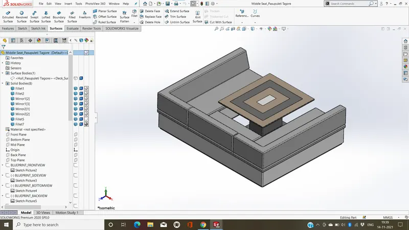
FEATURES USED TO CREATE MIDDLE SEAT :
- Sketch
- Blueprint
- Isert Part
- Boss extrude
- Chamfer
- Fillet
- Mirror
- Cut Extrude
- Appearances
sketch:
sketch is a 2D representation of the model.These are known as entities in solidworks,e.g.line,rectangle,circle etc....
Blueprint:
blueprint as in serving as a model or providing guidance especially a detailed plan or program of action
Isert Part :
Under Transfer, select any combination of items from the inserted part to be included in the derived part.
Boss Extrude :
Boss extrude feature will project a 3D model with the selected sketch. Using the 2D sketch plane to create a 3D model.
Chamfer :
chamfer tool creates a beveled feature on selected edges, faces, or a vertex.
Fillet :
In mechanical engineering, a fillet is a rounding of an interior or exterior corner or edge of a part design. Fillet geometry, when on an exterior corner/edge is of concave function,whereas a fillet on an interior corner is convex.in these cases, fillets are typically referred to as rounds.
Mirror :
Mirror tool to copy features and geometry about a planar surface. The mirrored copy can be independent, or dependent so it updates with the original feature or geometry.
Cut Extrude :
Extruded cut feature removes material from the part. The End Condition, Draft, and Thin Feature options are same as described in extruded boss/base and You can cut in both directions and mainly used for creating holes,channels,slots etc.....
Appearances :
appearance is the visual properties of a model, including color and texture,it's do not affect physical properties, which are defined by materials.
HULL :
A hull is the watertight body of a ship, boat, or flying boat. The hull may open at the top (such as a dinghy), or it may be fully or partially covered with a deck.
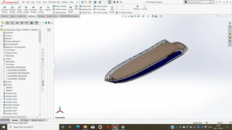
FEATURE USED TO CREATE HULL :
- Sketch
- Blueprint
- Projective Curve
- Lofted Surface
- Surface Trim
- Surface Extrude
- Surface Kint
- Surface Fill
- Shell
- Boss Extrude
- Cut Extrude
- Fillet
- Chamfer
- Sweep
- Revolve
- Dome
- Helix/spiral
- Linear Pattern
- Thin Extrude
- Mirror
- Thin Cut Extrude
- Delete/keep Body
- Split Line
- Surface offset
- Appearances
- Decals
sketch:
sketch is a 2D representation of the model.These are known as entities in solidworks,e.g.line,rectangle,circle etc....
Blueprint:
blueprint as in serving as a model or providing guidance especially a detailed plan or program of action
Projective curves :
to project a sketched curve onto a model face to create a 3D curve, that represents the intersection of two extruded surfaces generated by creating sketches on two intersecting plane.
Lofted Surface :
surfaces generated by multiple 3D Curves or existing edges creating a smooth tangency between the selected curves.
Surface Trim :
It's a handy tool to cut away, trim or sketch geometry quickly.
Surface Extrude :
extrude the boundary edges of a face of a solid body or edges of a surface body in a customized direction.
Surface Kint :
Knit Surface tool to combine two or more faces and surfaces into one.
Surface Fill :
It constructs a surface patch with any number of sides, within a boundary defined by existing model edges, sketches, or curves, including composite curves. You can use this feature to construct a surface to fill a gap in a model.
Shell :
The shell tool hollows out a part, leaves open the faces you select, and creates thin-walled features on the remaining faces or do not select any face on the model, you can shell a solid part, creating a closed, hollow model.
Boss Extrude :
Boss extrude feature will project a 3D model with the selected sketch. Using the 2D sketch plane to create a 3D model.
Cut Extrude :
Extruded cut feature removes material from the part. The End Condition, Draft, and Thin Feature options are same as described in extruded boss/base and You can cut in both directions and mainly used for creating holes,channels,slots etc.....
Fillet :
In mechanical engineering, a fillet is a rounding of an interior or exterior corner or edge of a part design. Fillet geometry, when on an exterior corner/edge is of concave function,whereas a fillet on an interior corner is convex.in these cases, fillets are typically referred to as rounds.
Chamfer :
chamfer tool creates a beveled feature on selected edges, faces, or a vertex.
Revolve :
Revolve have a 2D base shape but instead of extruding it, it is revolved around a specified axis and with a given angle.
Sweep :
sweep is a tool that creates a solid, a cut or a surface feature by moving a profile along a path.
Dome :
Dome is a curved formation or structure. It is shaped like half of a sphere.This is the shape of a dome, although most domes in nature are not perfectly rounded.
Helix And Spril :
spiral staircase has a centre column supporting the treads whereas a helical staircase has a void in the middle – it has no central column.
Linear pattern :
linear patterns to create multiple instances of one or more features that you can space uniformly along one or two linear paths.
Thin Extrude :
the sketched profile and creates a constant thickness in the sketch plane
Mirror :
Mirror tool to copy features and geometry about a planar surface. The mirrored copy can be independent, or dependent so it updates with the original feature or geometry.
Thin cut extrude :
thin features option gives the sketch a cut thickness and an extrusion depth
Delete/Keep Body :
For Bodies to keep or Bodies to delete, select bodies in the graphics area or from the Solid Bodies folder for Solid/Surface Bodies to Delete/Keep.
Split line :
2 to separate or be separated from a whole Part.
Surface Offset
faces that can't be offset the desired amount are automatically identified and highlighted in the tree.
Decals :
A decal is a 2D image applied to a model and it can used to create model details that you can represent with an image instead of with the model geometry, such as a car grill or a picture frame.
Appearances :
appearance is the visual properties of a model, including color and texture,it's do not affect physical properties, which are defined by materials.
GARAGE DOOR :
Garage door that covers the opening through which a vehicle enters and leaves a garage.
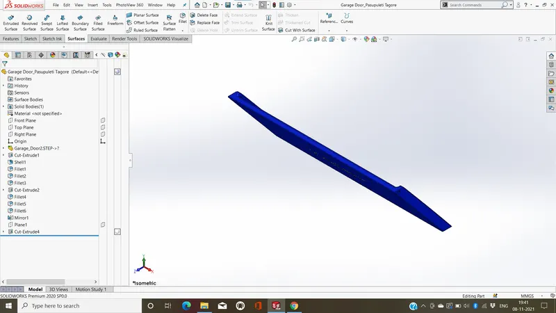
FEATURES USED TO CREATE GARAGE DOOR :
- Sketch
- Insert Part
- Cut Extrude
- Shell
- Fillet
- Mirror
- Sketch Text
- Appearances
sketch:
sketch is a 2D representation of the model.These are known as entities in solidworks,e.g.line,rectangle,circle etc...
Isert Part :
Under Transfer, select any combination of items from the inserted part to be included in the derived part.
Cut Extrude :
Extruded cut feature removes material from the part. The End Condition, Draft, and Thin Feature options are same as described in extruded boss/base and You can cut in both directions and mainly used for creating holes,channels,slots etc.....
Shell :
The shell tool hollows out a part, leaves open the faces you select, and creates thin-walled features on the remaining faces or do not select any face on the model, you can shell a solid part, creating a closed, hollow model.
Fillet :
In mechanical engineering, a fillet is a rounding of an interior or exterior corner or edge of a part design. Fillet geometry, when on an exterior corner/edge is of concave function,whereas a fillet on an interior corner is convex.in these cases, fillets are typically referred to as rounds.
Mirror :
Mirror tool to copy features and geometry about a planar surface. The mirrored copy can be independent, or dependent so it updates with the original feature or geometry.
Sketch Text :
The text is sketched along the outside edge of the face of the part, formatted, then cut.
Appearances :
appearance is the visual properties of a model, including color and texture,it's do not affect physical properties, which are defined by materials.
FRONT SEAT :
that is equipped with a restraining device or harness and can be fastened to the seating.
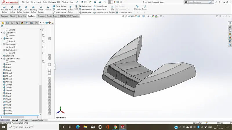
FEATURES USED TO CREATE FRONT SEAT :
- Sketch
- Blueprint
- Isert Part
- 3D Sketch
- Swept surface
- Surface Extrude
- Surface Trim
- Surfacer Fill
- Lofted Surface
- Surface kint
- Chamfer
- Revolve
- Cut Extrude
- Thin Cut Extrude
- Fillet
- Mirror
- Dome
- Appearances
Sketch:
sketch is a 2D representation of the model.These are known as entities in solidworks,e.g.line,rectangle,circle etc....
Blueprint:
blueprint as in serving as a model or providing guidance especially a detailed plan or program of action
Isert Part :
Under Transfer, select any combination of items from the inserted part to be included in the derived part.
3D Sketch :
A 3D sketch plane is a 2D plane that only exists inside the 3D sketch.When activated, sketching will happen exclusively on that plane and you will get behavior similar to when working in a 2D sketch.
Swept Surface :
Create planes for sketching the sweep profile, sweep path, and if necessary, the guide curves.
Surface Extrude :
extrude the boundary edges of a face of a solid body or edges of a surface body in a customized direction.
Surface Trim :
It's a handy tool to cut away, trim or sketch geometry quickly.
Surface Fill :
It constructs a surface patch with any number of sides, within a boundary defined by existing model edges, sketches, or curves, including composite curves. You can use this feature to construct a surface to fill a gap in a model.
Lofted Surface :
surfaces generated by multiple 3D Curves or existing edges creating a smooth tangency between the selected curves.
Surface Kint :
Knit Surface tool to combine two or more faces and surfaces into one.
Chamfer :
chamfer tool creates a beveled feature on selected edges, faces, or a vertex.
Revolve :
Revolve have a 2D base shape but instead of extruding it, it is revolved around a specified axis and with a given angle.
Cut Extrude :
Extruded cut feature removes material from the part. The End Condition, Draft, and Thin Feature options are same as described in extruded boss/base and You can cut in both directions and mainly used for creating holes,channels,slots etc.....
Thin cut extrude :
thin features option gives the sketch a cut thickness and an extrusion depth
Fillet :
In mechanical engineering, a fillet is a rounding of an interior or exterior corner or edge of a part design. Fillet geometry, when on an exterior corner/edge is of concave function,whereas a fillet on an interior corner is convex.in these cases, fillets are typically referred to as rounds.
Mirror :
Mirror tool to copy features and geometry about a planar surface. The mirrored copy can be independent, or dependent so it updates with the original feature or geometry.
Dome :
Dome is a curved formation or structure. It is shaped like half of a sphere.This is the shape of a dome, although most domes in nature are not perfectly rounded.
Appearances :
appearance is the visual properties of a model, including color and texture,it's do not affect physical properties, which are defined by materials.
ASSEMBLY OF SUNSEEKER PREDATOR YACHT :
The term mechanical assembly is most often referred to putting components together in an assembly line, but more specifically, it refers to creating a complete product that performs an intended function.For most operations, the behaviour of components is the same for both types. Adding a component to an assembly creates a link/mates between the assembly and the component.
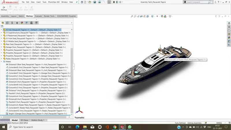
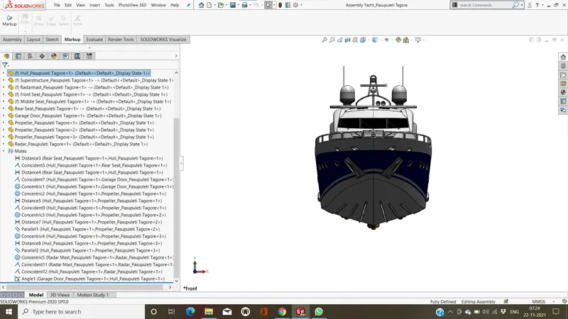
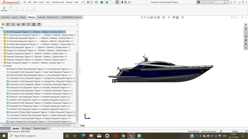
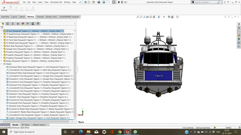
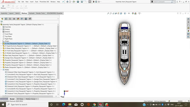
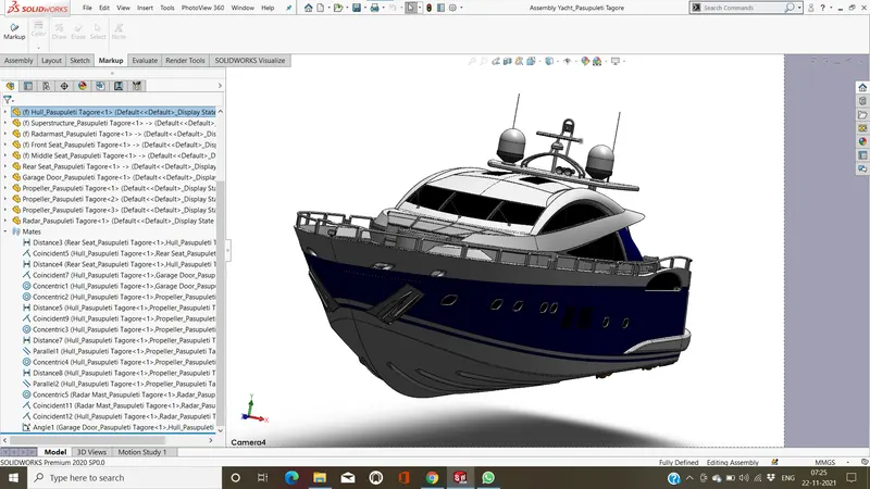
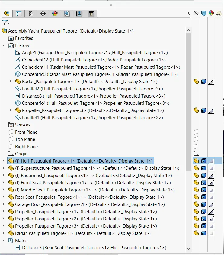
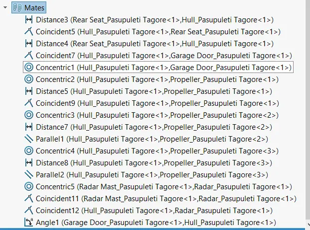
FETURES USED TO CREATE ASSEMBLY:
- Meats
- Inseart Components
Meats :
select the entities that you want to mate together for Entities to Mate . You can temporarily hide faces to select an obscured face by hovering over a face and pressing Alt.
Inseart Components :
Create a new assembly document by clicking New Standard toolbar.In an existing assembly by click Insert Components
PROCEDURE FOR ASSEMBLY THE YACHT:
- Initally open assembly document and save it.
- insert tha tha parts by using insert components tool.
- insert tha component one by one and give the possible links/metts condations.
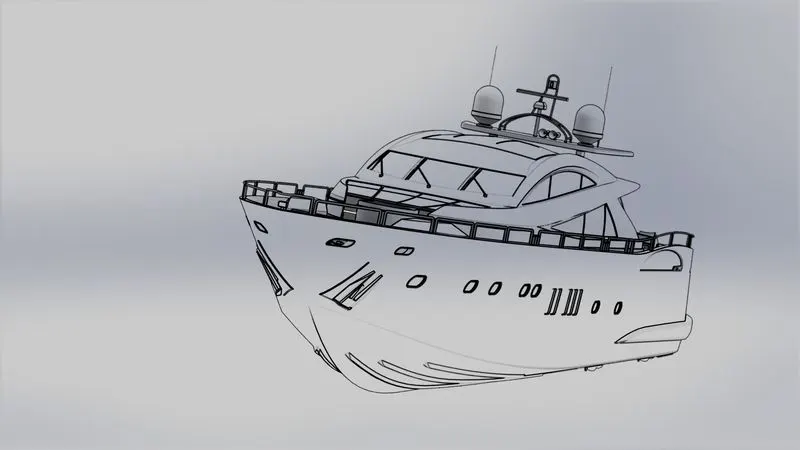
RENDIRING :
is add-in that produces photo-realistic renderings of models. The rendered image incorporates the appearances, lighting, scene, and decals included with the model.
RENDERING DONE BY TWO WAYS
- Photoview360
- solidworks visualize
RENDERING BY PHOTOVIEW360 :
PhotoView 360 is a visualization and rendering solution.and it's Providing a highly interactive environment for viewing designs as well as for creating photo-realistic renderings that can be used to showcase our design.
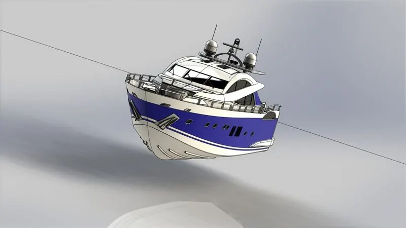
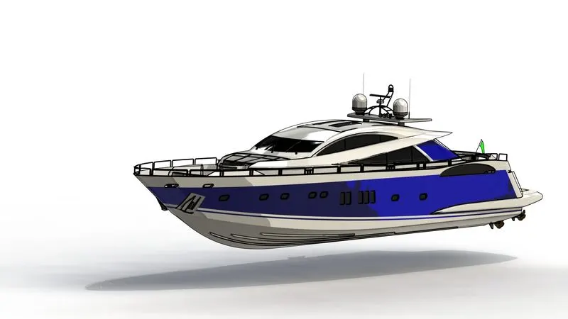
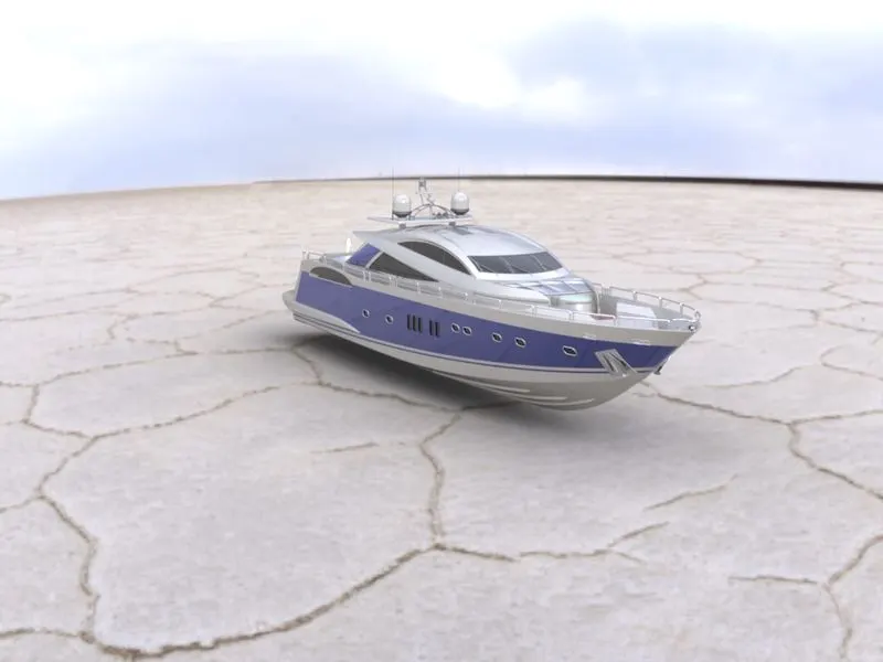
RENDERING BY SOLIDWORKS VISUALIZE :
Solidwork Visualize allows you to leverage your 3D CAD data to create photo-quality content in the fastest and easiest way,you can from images to animations, interactive web content, and immersive Virtual Reality. Bring your products to life. SOLIDWORKS Visualize is the “camera” for our design.

CONCLUSION:
- all part of Yacht are modeled,and insert tha assembly enevirnoment and assembled.
- good knowladge about all futers tools and rendering tools.
- learn how to render image by adding types of material,camera view,and enevirnoment.