Week 8 - Challenge 3 - Switch Bezel Design
SWITCH BEZEL DESIGN:-
This report demonstrates the design of an automotive plastic component - Dooe switch bezel using industry principles such as Draft angles,Draft analysis,determining and implementing of tooling axis,Class A,Class B and Class C surfaces.The component is designed using surface design and solid design techniques in CAD package CATIA V5.
The terms are breifly explained below
- Draft is an angular tapering given at the design stage to every plastic component that has to be manufactured.
- It is given in the direction of the mold component.
- The Draft allows the part to release easily from the mold without creating friction between the surface of component and core and cavity plates.
- When a palstic component colls down inside the mold, the natural tendency is to shrink and attach to the core or cavity half.
- The movement of mold opening causes friction on the walls of the component as welle as the core/cavity blocks.
- This reduces the life of the mold as well as the component itself.
- The component may also have rough surface finish as well as weak surface due to this.
- This problem can be solved by giving draft to the component.
- Most applications require minimum draft angles of 0.5 deg to 1 deg, however 3 deg draft angles are widely accpeted for cost saving purpose.
- 7 deg draft angles are given to textured surfaces like Instrument panels.
- Minimum possible draft angles are given to screw bosses,ribs and stiffners due to their critical nature.
TOOLING AXIS:
Tooling axis is the direction in which the mold opens and closes.Part Drafts are given along the axis.
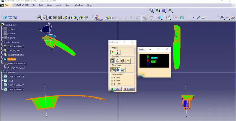
Draft Analysis:
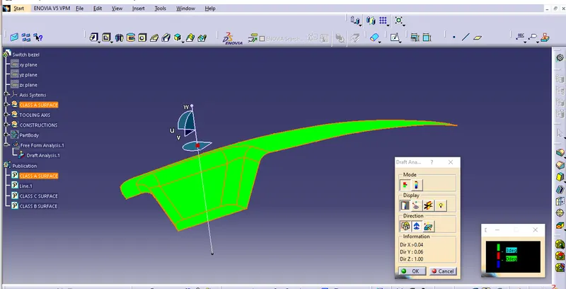
- Draft analysis is a tool in CATIA which identifies the zones which deviates from the specified values of angles along a defined draft direction using colour codes.
- It highlights the regiions of draft using colours.
- Draft analysis is the first step performed after recieving the class A component.
- Draft analysis should be passed in order to make the plastic component manufacturable.
- Acceptable Draft angles are used as range for Draft analysis.
Class A Surface:
- In automotive design,a class A surface is set of freeform surfaces of high efficiency and quality.
- It os the visible aesthetic surface of any automotive component.
- Class A surface refers to those surfaces which are visible and abide to the physical meaning in a product.
CLASS B SURFACE:
- Classs B surfaces are engineering surfaces which are invisible to the eyes are often on the back side of the Class A surfaces.
- It is mainly the thickness of the component or Class A.
CLASS C SURFACE:
- Class C surfaces are connectors betwween Class A and Class B.
- This surface connects both A and B surfaces along the toolking axis.
- It contains the draft as per design.
PROCEDURE IN DESIGNING SWITCH BEZEL
Step1: Design Check on recieved Class A
- After recieving the CLass A surface for the switch bezel, Check the connectivity of the surfaces on it.
- Use join operation,boundary operation and disassmeble.
- The check is over if any discontinuities do not arise.
Step2: Determine the tooling axis
- Identify the faces which can potentially create problem while manufacturing.
- Surfaces at angles along a desired tooling axis.
- Extract a plane surface and create a point on its center for axis system creation.
- In this case Z axis can be the possible tooling axis direction.
CLOSED SURFACE DRAFT ANALYSIS: