Photo Realistic Rendering
Modelling of American Chopper in Solidworks
Introduction:
Solidworks is one of the prominent modelling software used to model 3D parts usind 2D sketch. It also have the option to specify the material and look for the model which we create. It has other Add-in features like Photoview360 which helps in rendering the model we have created in a more realistic appearances.In this project we have learnt detailed design of american chopper parts and assembling them, then rendering the final chopper in a maximum realistic way accordingly.
Objective :
The main objectives of this project are:
- To create the individual parts of chopper using Solidworks.
- To assemble all the individual parts in a chopper
- To know the application of decals,appearances,lights and camera etc.
To create photorealistic model and render it using photoview 360 and solidworks visualise.
Design Methodology :
CHOPPER:
1)Modelling of Individual parts:
- The following are the parts modelled with the help of solidworks:
- Kickstand,Chain,Fenders,Engine,Chasis,Wheels,Front Fork,Oil tank,Gas tank
2)Assembly:
- Mates
3)Rendering:
- Decals
- Photoview 360
- Solidworks visualise
Kickstand :
It is also known as side stand.It is used to rest the chopper on ground while it is needed.
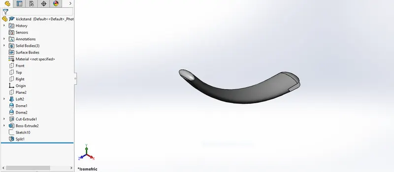
Features used to create kickstand:
- Sketch
- Loft
- Dome
- Extrude boss
- Extrude cut
- Fillet
- Split
Sketch:
The sketch is a 2D representation of the model with the help of sketching entities like ellipse,line,spline,circle,rectangle,3 point arcs etc.
Loft:
The Loft feature allows you to generate complex geometry.we can use the sketches ,faces or edges, the loft interface the cross section are termed as loft profiles.
Dome:
It can be applied to the faces where it can be one or more planar and non planar faces.It can be applied to irregularly shaped contours also.
Extrude Boss/base:
It will help to turn a 2D sketch in to a 3D one.
Fillet:
It is used to give a rounded shape for either internal or external edges and faces on multiple bodies with one command.
Split:
We can use this to split the face or surface with a reference sketch added.It can be also used to split faces on multiple bodies on one command.
Procedure followed to create a model of Kickstand:
- Open a new soliwards part file.
- Change the names of the sketch planes as follows:
1.Front plane-Front plane
2.Top plane-Top plane
3.Right plane-Mid plane
- Create a 2D sketch on front plane as per given dimensions and make sure that sketch is fully defined by giving the relative relations.
- Then select the mid plane and start sketch
- There will be a new plane created and ellipse is drawn accordingly on the new plane.
- Then the loft command is used between the sketches to create loft for kickstand.
- Then rectangle is drawn on the the midplane to cut parts with the help of extrude cut command to cut parts which are not needed
- Then the dome feature is applied to the smaller face of the kickstand to make the face round and smooth.
- Fillets are applied for the edges as of required radius.
- Then finally the parts is saved as Kickstand.
Transmission Belt:
This is used to transmission power from engine to gear box.
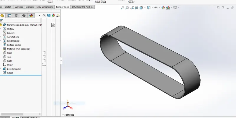
Features used to create transmission belt:
- Sketch
- Offset
- Extrude
- Fillet
- Appearances
Offset:
It is used to offset the sketch entities for certain dimension and in required direction. It can not only offset lines, iit can offset splines,arcs,model edges etc.
Procedure to create a model of Transmission Belt:
- Open a new solidworks part file.
- Select the front plane and start sketching.
- A 2D sketch is created on front plane with a dimensions required and also by making sure that the sketch is fully defined by adding necessary relations.
- Even an offset command command is used to replicate the sketch for certain dimension.
- Then the sketch is closed and an extrude command is used for converting 2D sketch in to 3D one.
- Fillet is added to the belt as per dimensions given.
- Then finally the model is saved as Transmission belt.
Front Fender:
It is located above the front wheel and mounted on the front fork toprotect the rider and other parts from debris and other invasive particles.
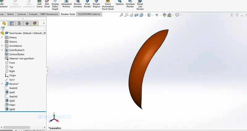
Features used to create fender:
- Sketch
- Offset entities
- Trim entities
- Revolve
- Dynamic mirror entities
- Split
- Appearances
Revolve:
To create a sketch that contains one or more profiles and a reference line or axis which is used to revolve.
Dynamic Mirror:
It is used to mirror the preketched entities with respect to some reference line or plane.
Rear Fender:
It is placed above the rear wheel and mounted on the part of chasis which as same use as that of front fender.
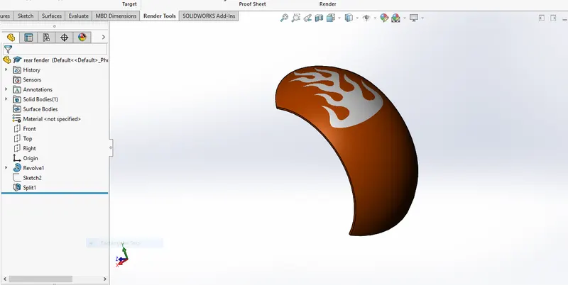
Features used to model Rear Fender:
- Sketch
- Offset Entities
- Trim Entities
- Revolve
- Appearances
Chain:
Chain is a type of transmission system which is used to transmit power from the engine to rear wheel. The sprocted which is connected to the shaft is used to transmit power to the chain.
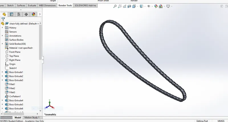
Features used to create Chain
- Sketch
- Trim
- Blocks
- Fillet
- Extrude
- Curve Driven Patterns
- Appearances
Trim Entities:
It is used to trim the sketch entities which are not needed for our sketch as per our required desing.We can make blocks, save them or edit them as per our necessary .
To make chain blocks:
1.Create a sketch
2.Select make block
3.Select the entity you want to save as a block.
4.Click ok and save for first block in a required destined folder.
5.Repeat the same steps as we used in 2ND and 4RTH step to create an another block.
6.With the sketch in edit mode and with necessary relations. Finally save the part.
Patterns:
Here in this case we use the curve driven pattern along the spline we have created as per our necessary instances for the chain design.
Oil Tank:
The oil tank is used to store the oilwhich is required to run the engine smoothly.It is a hollow part where the thickness is given by 3mm.
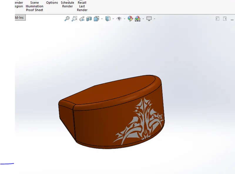
Features used to create oil tank:
- Sketch
- Boss Extrude
- Combine
- Fillet
- Shell
Shell:
The shell feature is used to define the thickness of thin and thick shell elements.
Combine:
It is used to manually combine two bodies likke by addind or substracting as per our need.
Pedal:
It is the external part attached to chasis.It is used to place the rider foot for adjsuting gears and they provide riding comfort too.
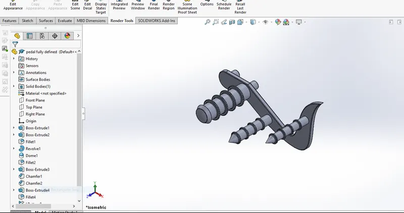
Features used to create Pedal:
- Sketch
- Extrude
- Fillet
- Linear pattern
- Dome
- Chamfer
Chamfer:
A cut on the edge or corner of something that give it a little slopy structure.
Linear pattern:
It is used to pattern the bodies linearly.
Front Wheel:
A wheel is a circular block made of steel/alloy material.On the top the wheel the tyre is covered.The tyre is made up of rubber and it has threads all around the tyre which helps in friction on roads.
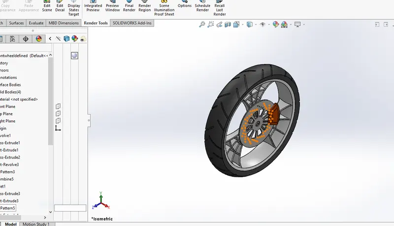
Features used to create Front Wheel:
- Sketch
- Revolve
- Trim
- Sketch fillet
- Boss Extrude
- Revolve cut
- Linear Pattern
- Chamfer
- Cut Extrude
- Circular pattern
Circular Pattern:
It is used to create the pattern of spokes and the pattern of groves created inside the rim.It is also used to create holes on the rotor.
Rear Wheel:
It is connected to the engine by chain.
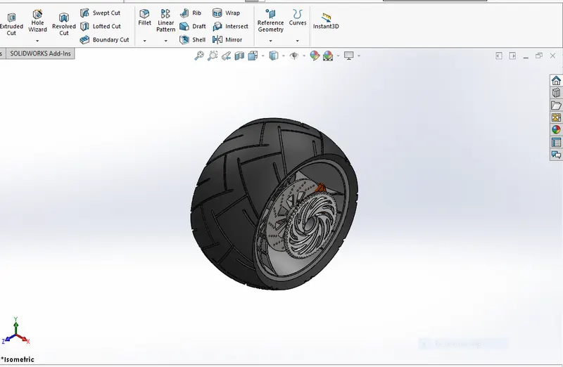
Features used to create Rear Wheel:
- Sketch
- Revolve
- Trim
- Sketch Fillet
- Extrude Boss
- Planes
- Revolve cut
- Circular Pattern
- Chamfer
- Fillet
- Extrude Cut
Front Fork:
Maximum Motorcycles today uses telescopic forks for the front suspension.The forks are large hydraulic ahock absorbers with internal coil springs.They allow the front wheel to react to the imperfections they gonna face on the road while isolating the rest of motorcycle from the motion.
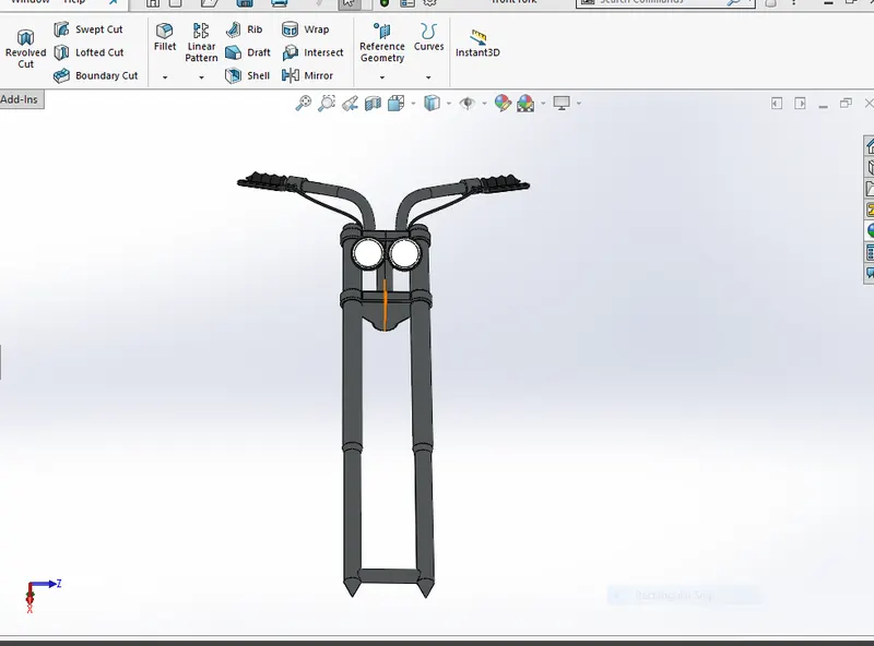
Features used to create Front Fork:
- Sketch
- Extrude
- Trim
- Revolve
- Split
- Move/Copy Body
- Dome
- Mirror
- Combine
- Projected Curve
- Sweep
Move/Copy Body:
It is used to move body from place to place accordingly.
Mirror:
By using the mirror bodies option, we can mirro the the bodied which are sketched on one side with respect to a reuired plane or a sketch for the selective bodies seperately.Then the parts are manually combined.
Projected Curve:
It is used to get a required 3D curve with the help of TWO 2D curves.
Sweep:
With a sweep option,we can create a shape by moving a 2D sketch profile along a 2D or 3D sketch path.
Chasis:
A chasis or a frame which forms the skeleton of our motorcycle.All the parts like wheels,tank,fuel tank,seats,handle bars etc are attached to this chasis which gives a motorcycle in terms of strength and an capability to move well.
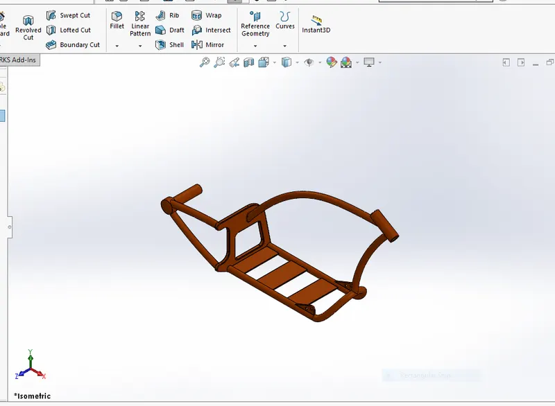
Features used to create Chasis:
- Sketch
- Offset
- Convert Entities
- Project curve
- Trim
- Sweep
- Split
- Revovle
- Cut Extrude
- Fillet
- Combine
Engine:
Engine is the prime mover of the bike.The engine converts the chemical energy from the fuel into the heat energy and then heat energy is converted in to mechanical work. In motorcycles the mechanical work is in rotational motion.This rotational motion is transmitted to wheel with the help of chain and sprocket through the gear box and clutch mechanism.
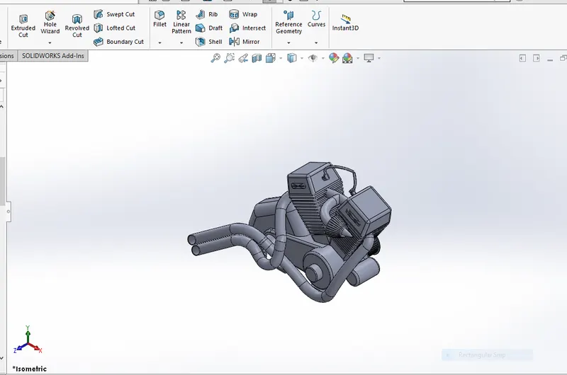
Features used to create Engine:
- Sketch
- Trim
- Revolve
- Boss Extrude
- Extrude Cut
- Offset
- Dome
- Fillet
- Projected Curve
- Composite Curve
- Sweep
- Mirror
- Circular pattern
- Split
Composite Curve:
This feature is used to join two curves and make them as single curve as required for our design.Like combining the projected curve with the other.
Gas Tank:
It is used to store gas and it gives gas to engine when it is required.
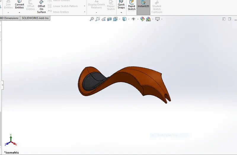
Features used to create Gas Tank:
- Trim
- Projected Curve
- Sweep Surface
- Loft Surface
- Fill surface
- Surface trim
- Surface Knit
- Sweep Cut
- Fillet
Loft Surfaces:
Loft surfaces are surfaces are generated by multiple 3D curves or existing edges creating a smooth tangency between the selected curves.
Sweep Surfaces:
Sweep surfaces are surfaces that are generated by a section curve positioned along the path.
Fill surface:
The fill surface constructs a surface path with any number of sides with in defined boundary conditions by the existing model edges
Surface trim:
Primarily used to cut away the material from a surface.
Surface Knit:
It is used to knit two free edges/open edges of the surface together.It also reduces the gap between the edges of the surfaces.
ASSEMBLY OF THE CHOPPER:
- Firstly the chasis part is inserted in the assembly by using insert parts option.After that the part is inserted in the assembly environment and click ok to the chasis.
- After that parts of the chopper are inserted into the assembly and given possible mate conditions.
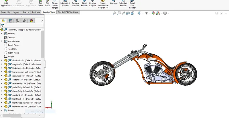
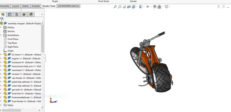
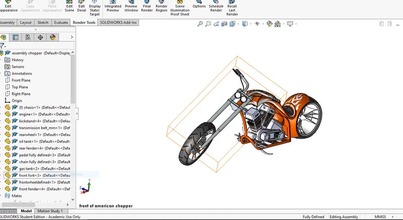
Features used to assemble chopper:
- Inserting parts
- Mates
Mates:
Mates create geometric relationship between the assembly components.As we add mates,we define the allowable directions of linear or rotational motion of the components.We can move a component within its degree of freedom,visualising the assembly behaviour.
RENDERING:
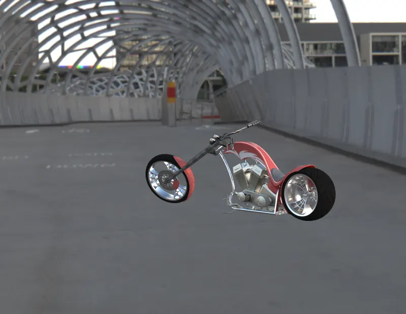
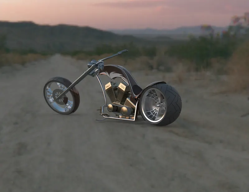
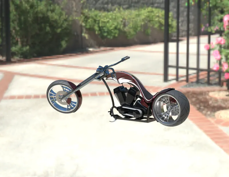
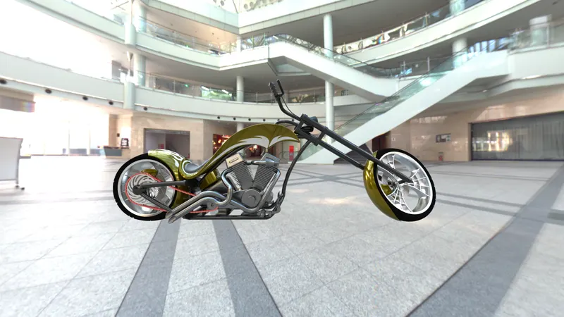
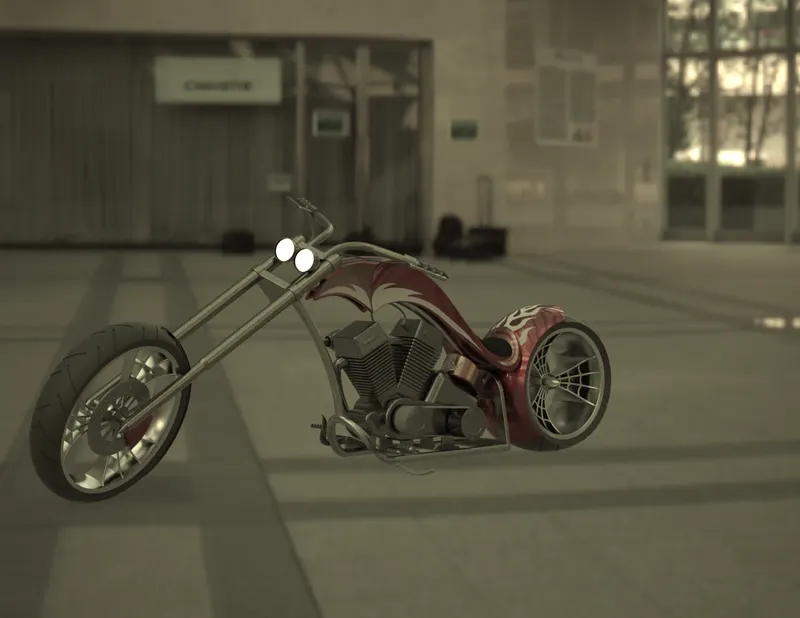
- Rendering is a process of creating realistic images of the photorealistic model with the environment.
- Rendering has been done in two ways in solidworks.
- Photoview 360
- Solidworks Visualise
In the photorealistic model some of the mate conditions and positions are changed to render realistic models.
Then, the photorealistic model is rendered into realistic images with different views.
Photoview 360:
Photoview 360 is a visualisation and rendering solution includes with solidworks.Providing a highly interactive environment for viewing designs as well as for creating photo-realistic rendering it can be used to showcase our designs as well.
Solidworks Visualise:
Solidworks visualise provides a suite of stand alone software tools that combine industry leading rendering capabilities features and workflows,allowing easy and fast creation of visual content that communicates a designs vision,passion and emotion.
CONCLUSION:
- The parts of the chopper are modelled.
- The parts are inserted into the assembly environment and the chopper is assembled.
- The realistic image was rendered with the use of the photoview 360 and solidworks visualise.