Radar Mast & Final Assembly of Yacht
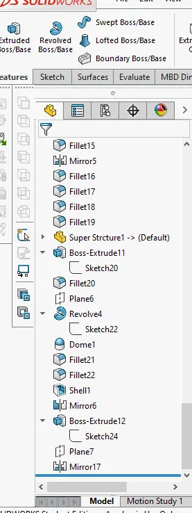
RADAR MAST:
MODELLING OF YACHT IN SOLIDWORKS:
Introduction:
Solidworks is one of the prominent modelling software available.This software is mainly used to model 3D parts using 2D sketch.It also has the option to specify materialand look for the modelwhich we create. It has other Add-in features like photoview 360 which helps in rendering final model to make that looks more realistic.In this project we learnt about detail designing of Yacht,Assembling them and rendering the final yacht model after the assembly.
Objective:
The main objective of this projrct are:
- To create individual parts of yacht using solidworks.
- To assemble all the individual parts to make final yacht model.
- To know the application of Decals,Scenes setup,Lights,Camera etc.
- To create realistic model and render it using Photoview 360 and solidworks visualise.
Design Methodolody/Approach:
YACHT:
- Modelling of Individual parts:
- Hull
- Propeller,Radar
- Front seat
- Middle seat
- Rear seat
- Superstructure
- Radar Mast
- Assembly:
- Mates
- Rendering:
- Photoview 360
- Decals
- Soliworks visualise
PROPELLER:
It incluse a set of vanes which rotates on shaft,power provided by motor.
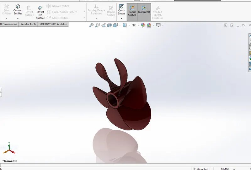
Feature used to create propeller:
- Sketch
- Revolve Boss/Base
- Loft
- Extrude Cut
- Fillets
- Pattern Circular
Sketch:
The sketch is a 2D representation of model.These are known as sketch entities in solidworks.
Ex:Line,Rectangle,Spline,Sketch Fillet etc
Revolve Boss/Base:
Create a Sketch that contains one or more profiles and a centre line or an edge to use as the axis aroubd which the feature revolve tools.
Loft:
The loft feature allows you to generate complex geometry.It does this by interpolating surfaces between various cross section of the model.These cross sections can be sketches,faces or edges.In the loft interface the cross sections are considered as loft profiles.
Extrude Cut:
This is feature is used to remove materials from the 3D model.It is just an opposite in the workfunction that od extrude boss.You can cut in both directions and mainly used to create holes,slots etc.
Fillet:
This feature creates a rounded internal or external face on the part.You can fillet all the edges of a face,loops etc
Pattern(Circular):
The Circular pattern allows you to create patterns around a circular sketch or circular model with a specicifed circular reference.
Procedure Followed to create a model of propeller:
- Open a new solidworks part.
- Select Right plane and start sketching.
- Then 2D sketch is created with a given dimensions and by giving realtions,making sure that sketch is fully defined.
- Then the revolve feature is used to create a revolved sketch.
- In order to create vanes, the top plane is selected initially and start sketching.
- A 2D sketch is created with the help of sketch entities like rectangles and centre lines.
- A new plane is added with a top plane reference at a specified distance.
- A 2D sketch is created on a new plane in order to sketch vane.
- Then the loft feature is used to create a solid loft between two 2D sketches.
- A specified fillet is added for a vane edge with a given radius.
- Finally circular pattern feature is used to create patterns of vanes.
- Then Appearance is added to complete the propeller model.
RADAR:
It is used as navigational device where it can detect other physical bodies and land obstacles which are approaching at a particular distance and direction.
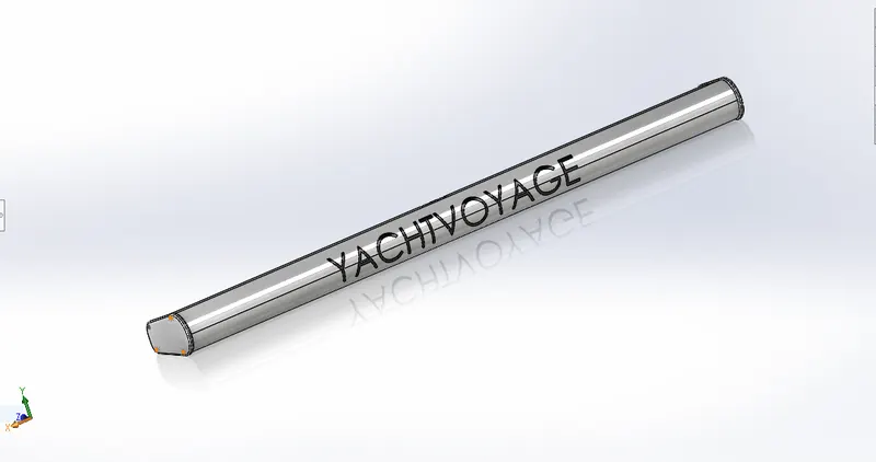
Features used to create Radar:
- Sketch
- Boss Extrude
- Extrude Cut
- Fillet
Sketch:
The sketch is 2D representation of model which are known as sketch entities in solidworks.
Ex:-Line,Spline,Rectangle,Circle etc.
Boss Extrude:
This feature is used to convert 2D sketch into 3D model.
Exturude Cut:
This feature is used to remone materials from the 3D model.It is just opposite to the extrude boss because its cuts the sketch profile while extruding.
Fillet:
This feature creates a rounded internal or external face on the part.You can fillet all the edges of face,loops etc.
Procedure used to create a model of Radar:
- Open the new solidworks part.
- Select right plane and atart sketching.
- Create a 2D sketch for a given dimensions and making sure that the realtions make the sketch fully defined.
- Use boss extrude for the specified distance.
- Add the fillets with a specified radius to make the edges round as needed.
- Select the particular surface to create another 2D sketch which should be extrude further to certain distance.
- Select the newly extrude surface and sketch a circle to extrude.
- Use sketch entities like polydon to give a required shape.
- Then do sketch driven pattern for the newly created 3D sketch.
- Mirror the create sketch across right plane.
- Select the required flat surface and sketch a circle to create a hole.
- Finally use sketch text to create a text markings on the model.
FRONT SEAT:
It is a seating model created using the solid works which is placed in the front side on the hull.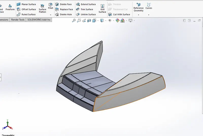
Features used to create Front seat:
- Sketch
- Insert Part
- Surface Sweep
- Surface Extrude
- Surface Trim
- Surface Fill
- Surface Loft
- Chamfer/Fillet
- Revolve Boss
- Extrude Cut
- Mirror
- Dome
- Appearances
Insert Part:
This feature is used to insert the parts which are previously created that will be used in the upcoming sketches.
Surface Sweep:
It is used to create a Surface using 2D sketch profile and a path.
Surface Extrude:
It is similar to our boss extrude where this can give a required extruded surface while creating our model.
Surface trim:
This feature is used to eliminate the extra surface while constrcuting the model with a given reference.
Surface Fill:
It is used to fill the surface by selecting the required edges in our 3D model.
Surface Loft:
This feature is used to give a nice surface with a help of edges and a given guide curves to finish the loft operation.
Dome:
This feature is majorly applied to faces.Select one or more planar or non planar faces whose centroid lied outside the face.This allows you to apply domes to irregularly shaped contours.
Chamfer:
A cut on the edge or corner of something tht makes it slope slightly rather being perfectly square.
MIDDLE SEAT:
It is placed on the middle of the yacht right in back of the superstructure on the hull.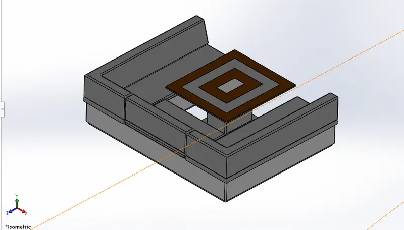
Features used to create the model of Middle seat:
- Insert Part
- Sketch
- Boss Extrude
- Chamfer/Fillet
- Mirror
- Appearances
REAR SEAT:
It is a seating model which will be placed on the back side of the superstructure right at the end on the hull.
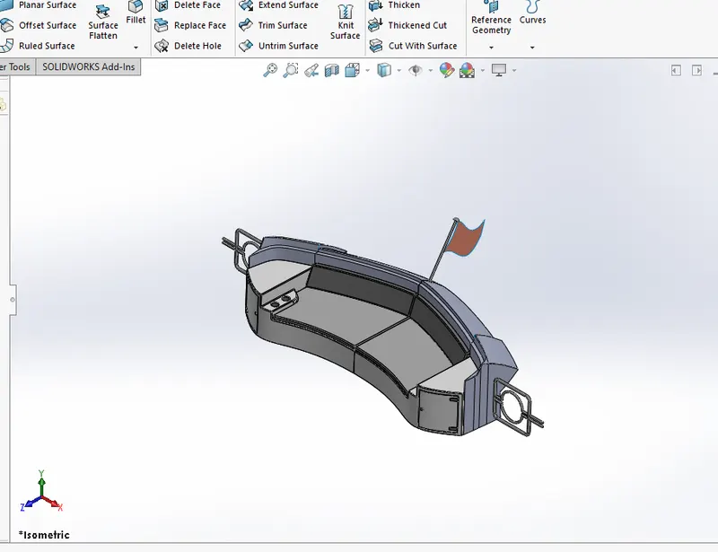
Features used to create the model of Rear seat:
- Insert Part
- Sketch
- Surface Sweep
- Ruled Surface
- Knit Surface
- Surface trim
- Surface Loft
- Surface Extrude
- Extend Surface
- Extrude Cut
- Appearances
HULL:
It is water tight body of the yacht.Hull may be open at the top or it will fully or partially covered by a deck.
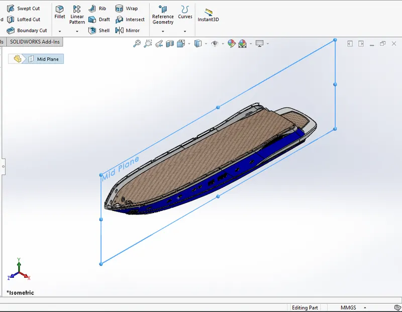
Features used to create the model of Hull:
- Sketch
- Blueprint Setup
- Projected Curve
- Offset Entities
- Surface Loft
- Surface Trim
- Knit Surfaces
- Surface Fill
- Shell
- Surface Extrude
- Linear Pattern
- Fillet/Chamfer
- Copy/Move
Projected Curve:
It is a kind of 3D curve which is projected based on the two different 2D sketches.
Offset Entities:
Offset one or more sketch entities,selected model edges or model faces by specified distance.
Shell:
The shell feature is used to determine the thickness of thin and thick shell elements.
Linear Pattern:
It is also same as circular pattern.The feature or the bodies are patterned linearly.
SUPERSTRUCTURE:
It is placed above the hull which covers partially or fully the deck surface.
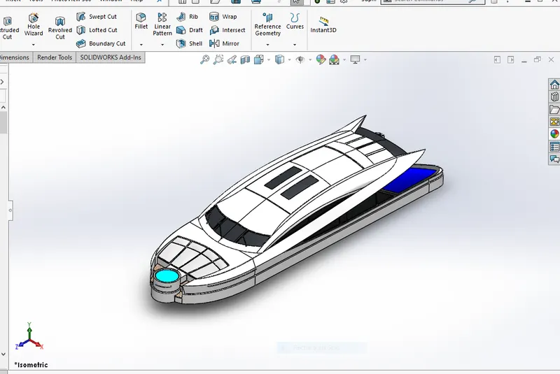
Features used to create the model of superstructure:
- Insert part
- Blueprint setup
- Sketch
- Surface Loft
- Surface Fill
- Surface Extrude
- Split line
- Surface Trim
- Projected curve
- Boss Extrude
- Swept Surface
- Offset Entities
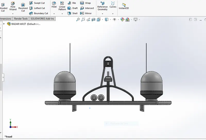
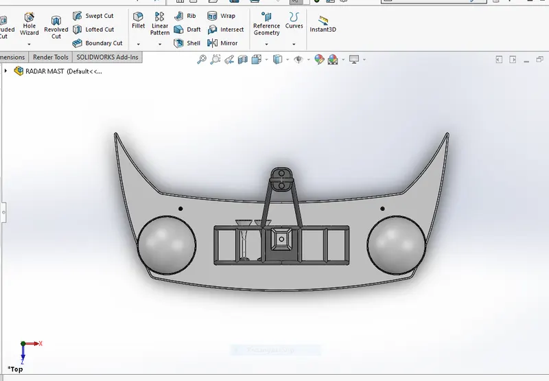
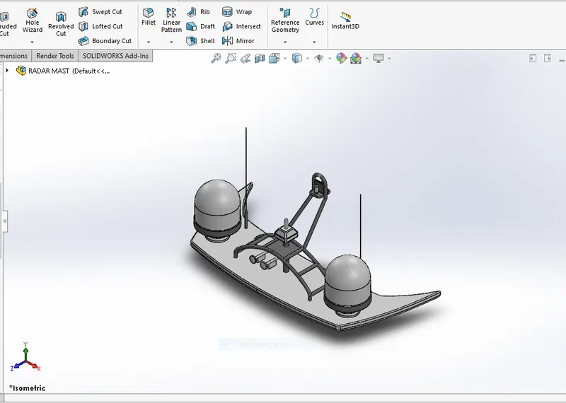
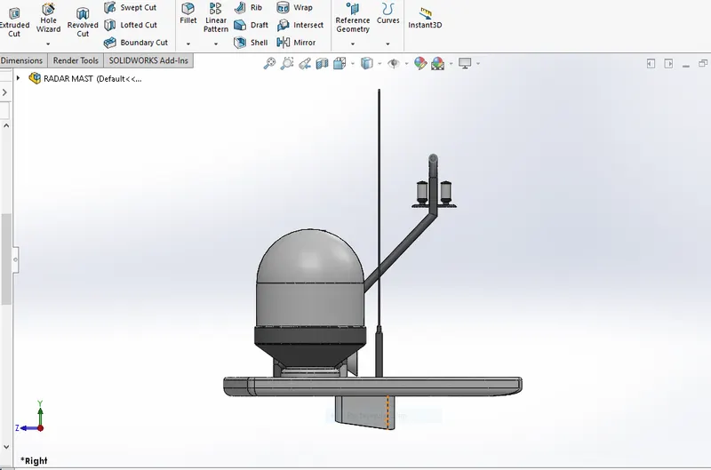
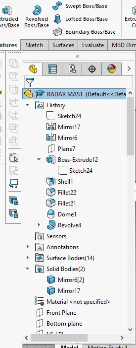
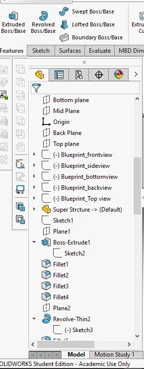
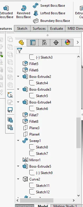
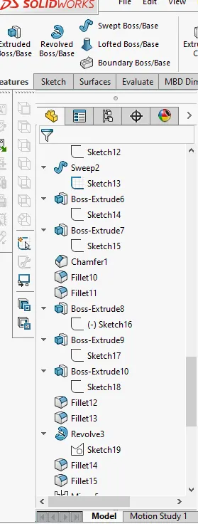
RADAR MAST:
It is a device used for navigational purposes which is placed on the top of the yacht where it can sense and give signal regarding foreign and physical bodies which are nearly approaching.
Features used to create the model of Radar Mast:
- Insert part
- Blueprint Setup
- Sketch
- Boss/Base Extrude
- Revolve Boss
- Mirror
- Fillet/Chamfer
- Swept Surface
- Extrude Surface
- Dome
- Shell
ASSEMBLY OF THE YACHT
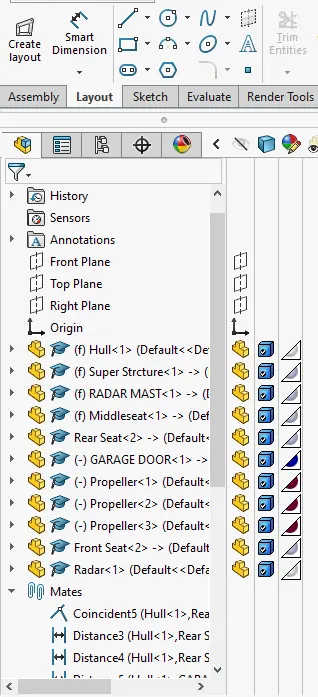
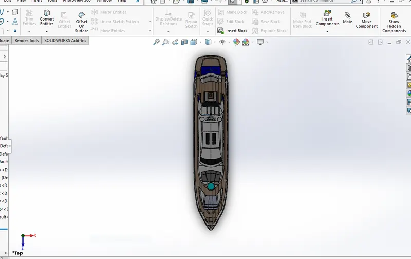
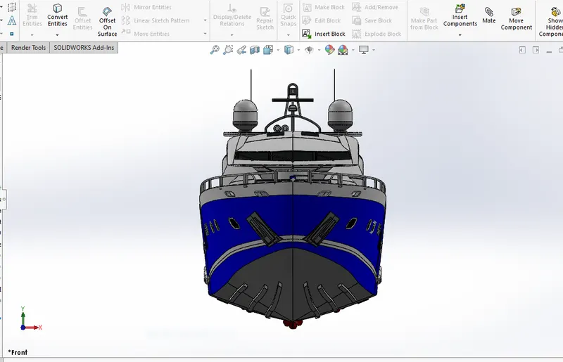
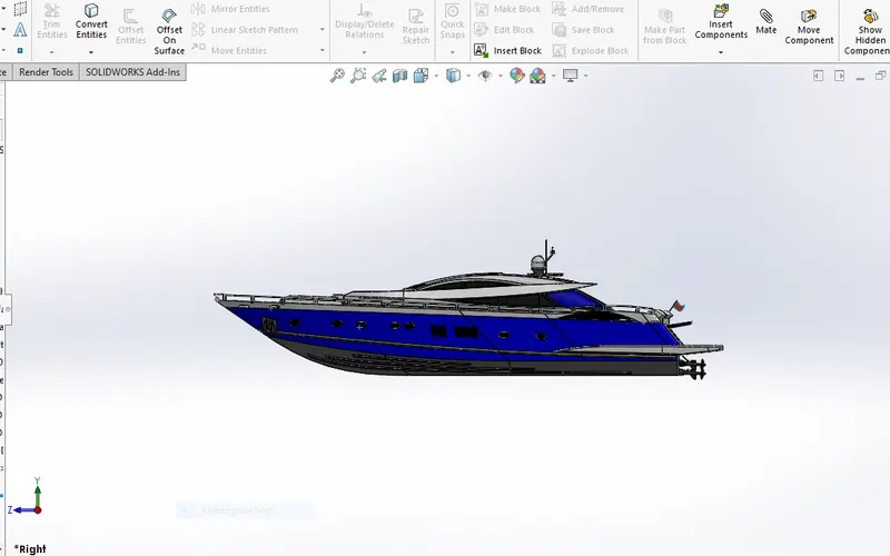
- Initially the Hull part is inserted in the assembly by using insert parts in the option.
- Next the Radar Mast, front seat and middle seat is inserted which will be placed with insert option itself.
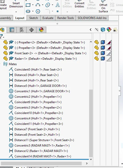
- Then the rear seat will be brought to assembly environment with the help of insert part option, then a concident mates will be used to specify its positionb on the hull.
- Finally the Garage door,Radar and the propellers are inserted with the help of concentric and coincident mates.
Features used to assemble yacht:
- Inserting Parts
- Mates
Mates:
Mates create geometric relationship between assembly components.As we add mates,we define the allowable directions of linear or rotational motion of the components.we can move a component within its degree of freedom,visualising the assembly behaviour.
RENDERING
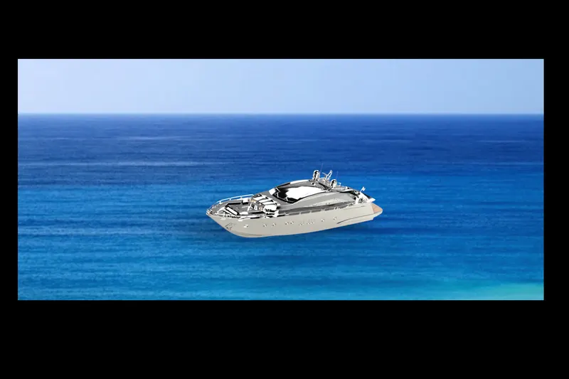
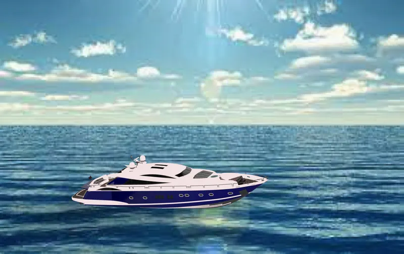
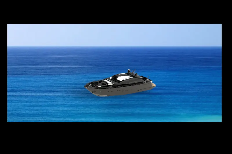
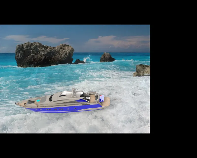
- Rendering is a process of creating realistic images of photorealistic images of the photorealistic model with the environment.
- Rendering has been done intwo ways in solidworks.
- Photoview360
- Solidworks visusalize.
In the photorealistic model some of the mate conditions and positions are changed torender realistic models.
Then,the photorealistic model is rendered in to realistic images with different views.
PHTOVIEW 360:
Photoview 360 is a visualization and rendering solution includes with solidworks.Providing a highly intersactive environment for viewing designs as well as for creating photo-realistic rendering.
SOLIDWORKS VISUALIZE:
It provides a suit of stand alone software tools that combine industry leadng rendering capabilities with visual design oriented features and workflows,allowing easy and fast creation of visual content that communicates a designs vision,passion and emotion.
CONCLUSION
- The parts of the yacht are modelled.
- The parts are inserted in to assembly environment and the yacht is assembled.
- The realistic image was rendered with the use of Photoview360 and solidworks visualise.