Week 8 - Challenge 3 - Switch Bezel Design
ABSTRACT:
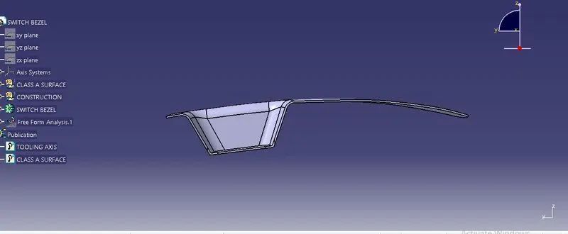
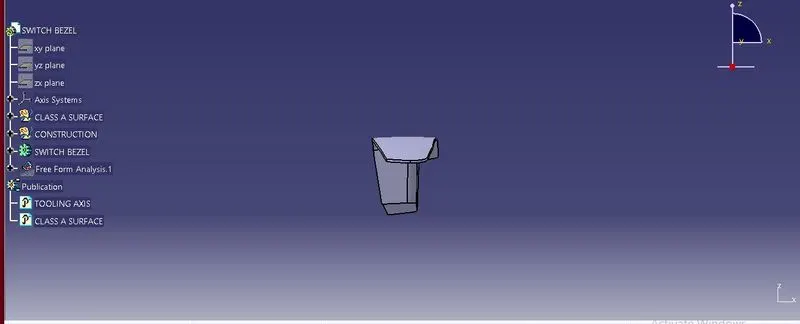
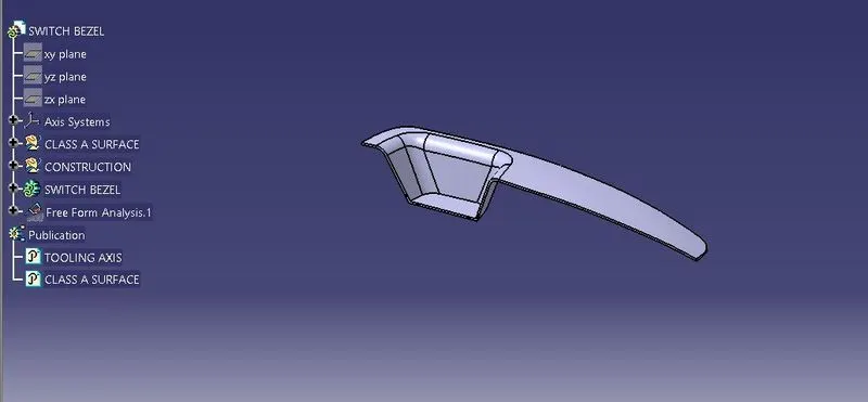
Create the Switch Bezel Plastic component through the given Class-A surface. To begin with, the tooling axis for the given Class-A Surface should be created meeting the requirements of the draft angle and at the end perform the Draft analysis on the model.
PROCEDURE:
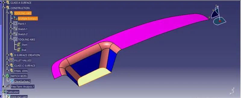
Determining the tooling axis for the given class A surface by using bisecting method .For creating the tooling axis for the given class A surface are as follows.
- first the direction was determined and then the base area as etracted using multiple extract option
- After creating the extract the point should be inserted to the surface for determining the axis.
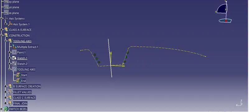
- intersection between the side walls taken and then lie as inserted to the intersction line and centre line as created by the line bsecting method. by choosing the to drawn lines.Bysecting lines are the lines which will be created between two line bisecting them and it is the major key factor in creating the tooling axis.
- After crateing in y direction intersection was created to the another direction and line is craeted to that direction. and another lie as created to that line ith an angle of 3 degree.
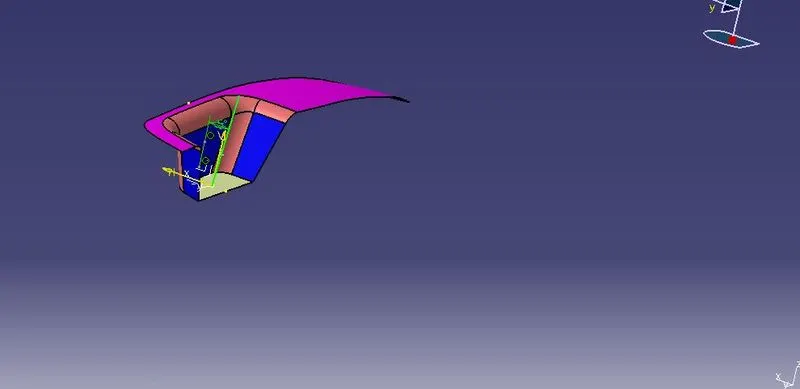
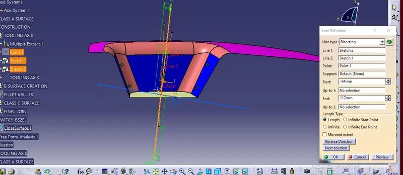
- After creating the x and y line the tooling line is created using the line bisecting option . In that option the x line and y line was selected with the point1. that line as the tooling axis for the switch bezel.
draft analysis of class a surface:
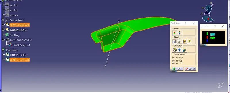
for the draft analysis the part is changed to material mode and the compass option was selected in the draft analysis option and draged and placed in the tooling axis and the material is selected. In another pop menu the colour coded combination was shown which will show the condition of the class A surface. If it is in the green colour the surface is ok and red means zero and blue determine the negetive value.
B surface creation:
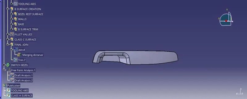
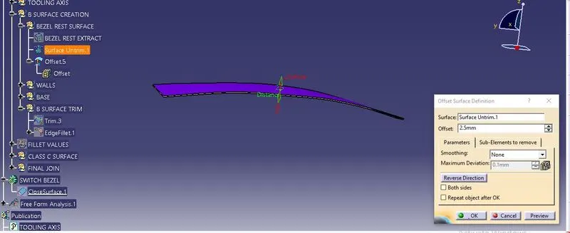
For creating the B surface all the surfaces as extracted on by one and offseted to 2.5mm for the final thickness of the part.
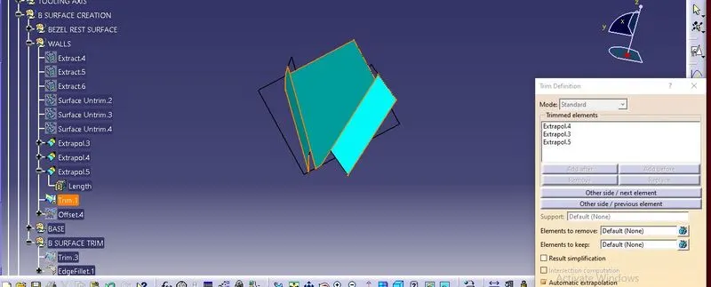
For the walls and base the surfaces are extracted, extraplated and trimmed .
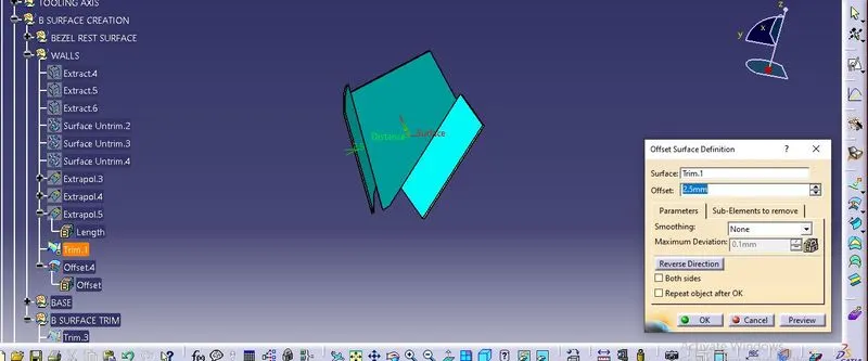
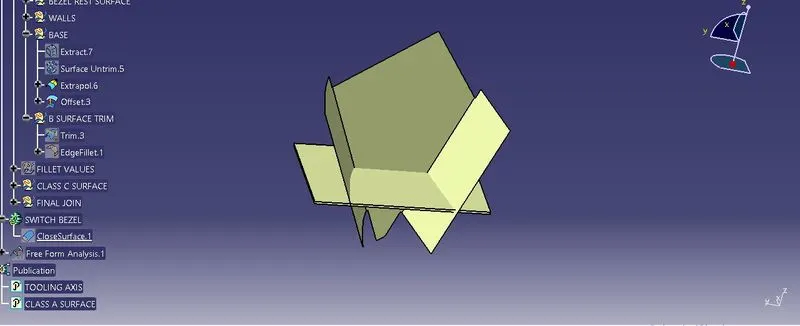
Final trim for the B surface
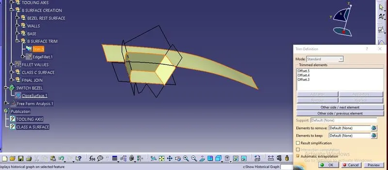
All the offseted surfaces are trimmed and edge fillet of 11.5 mm was added to get the 2.5 mm thickness of the part.
CLASS C SURFACE:
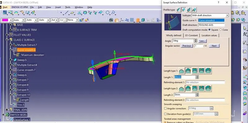
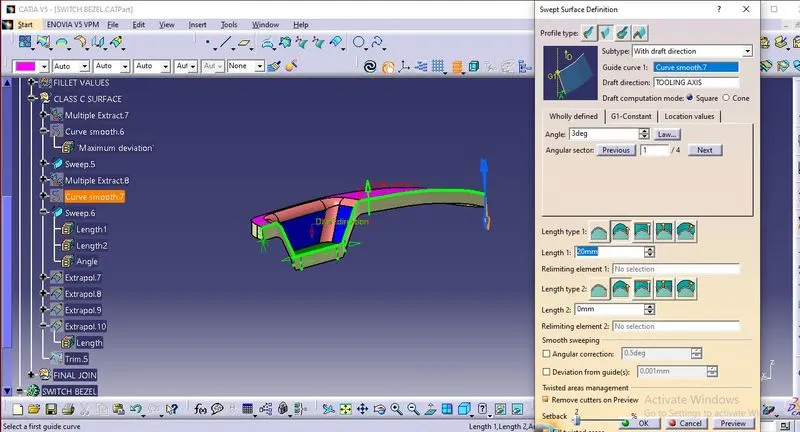
For the C surface the edge of the class a surface was extracted and made into smooth curves and swept at an angle of 3 degree and extraplated and trimmed
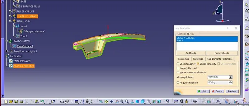
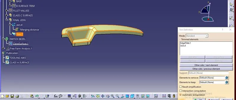
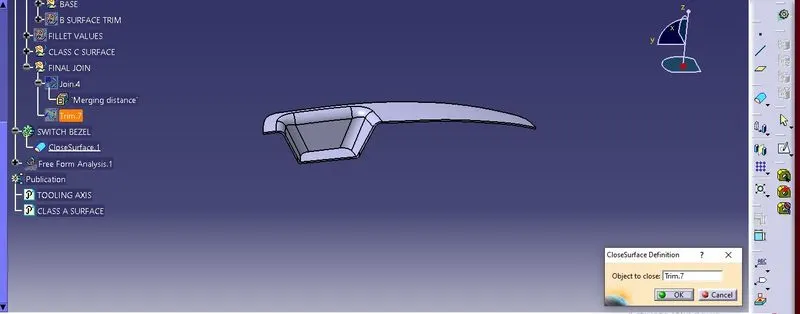
FINAL JOIN
FINAL DRAFT ANALYSIS:
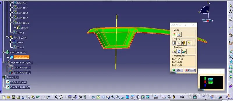
It lies for 3 degree angle of draft so it can be manufacturable.