Week 8 - Challenge 2 - Base Bracket Design
OBJECTIVE:
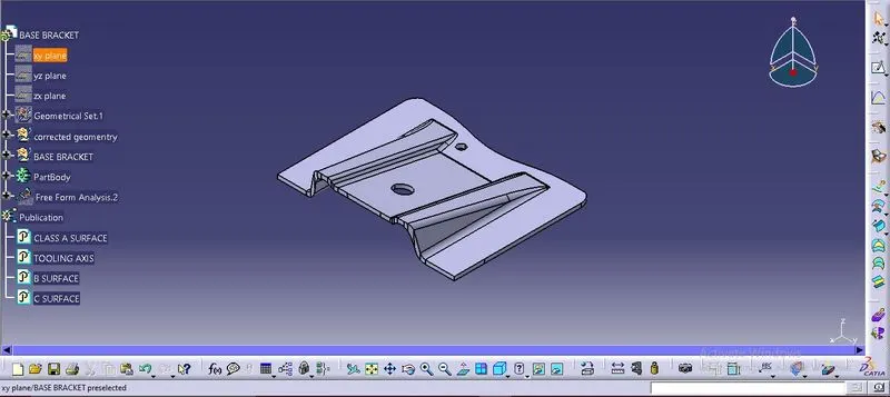
To create the Base Bracket Plastic component through the given Class-A surface, by using tooling axis and draft analysis method.
PROCEDURE:
1. Dummy tool axis creation:
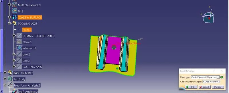
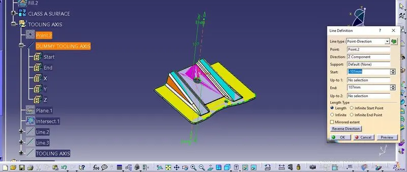
On the given class A surface, First we have to create a dummy tooling axis so that we can find the actual tooling axis. For creating the dummy tooling axis the point is inserted to the circle.Followed by the point a line is inserted to the point in the direction of z axis, which will act as the dummy tooling axis.
2. Tooling axis with the help of line bisect method:
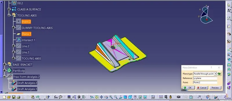
The tooling axis should be determine by the core and cavity movement. which help to make the product to manufactured without adding side core to it. For creating the tooling axis,first we have to create a plane with parallel to the point type and along xy plane. followed by intersection was created with the class a surface and the plane1.
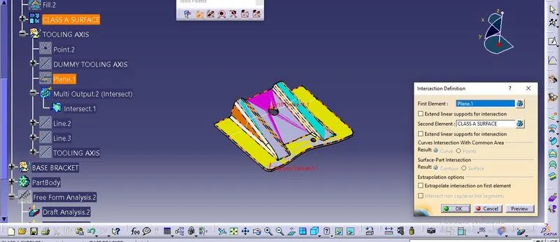
After creating the intersection line the tappered angle to the tooling axis in the intersection line should be extended to created the tooling axis. with the help of the extended line the tooling axis was created using the line bisecting option. refer the image below.
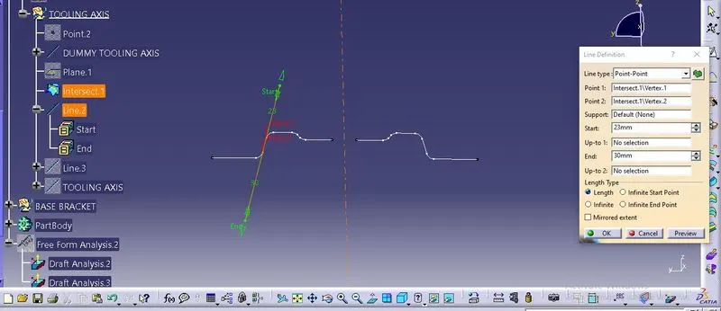
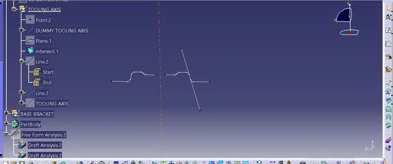
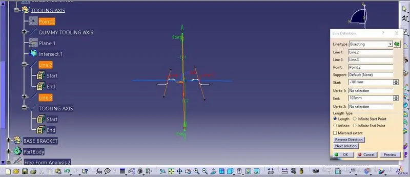
3.draft analysis for the given class a surface
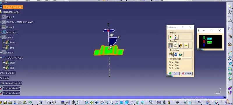
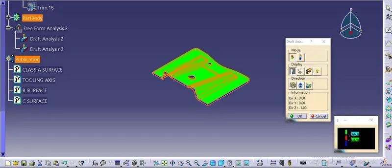
Draft analysis was done using feature draft analysis option. for the draft analysis the surface should be in material mode. The pop up menu will open when the draft analysis is clicked and it has another box which shows the colour varient scale. The compass option was used to define the new cuurent draft direction and the compass was allined in the tooling axis .After its paced the surface was clicked. If the surface is 3 degree it will show the surface in green colour and if its in red its 0 and blue means negative value.
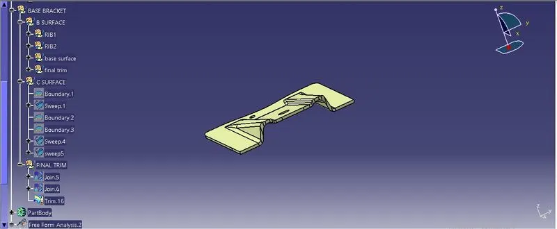
4. Creation of class B and class C surface:
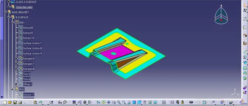
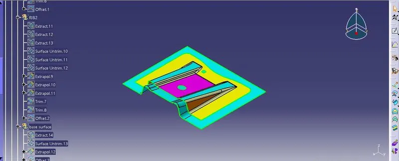
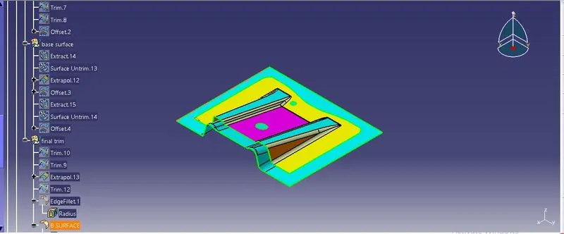
class c surface creation
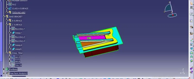
5. part creation
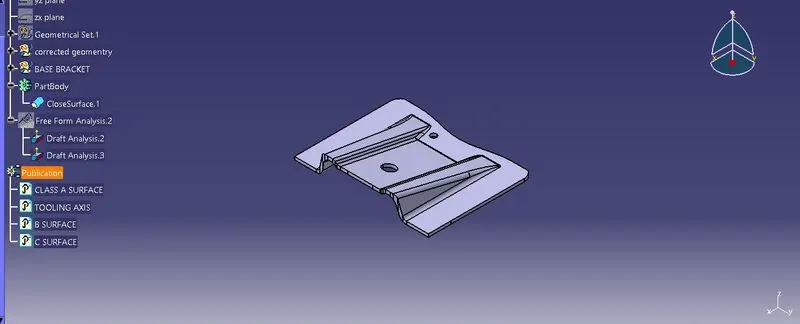
after the final trim the surface should be thicken by part part design and closed surface option.
6. final draft analysis
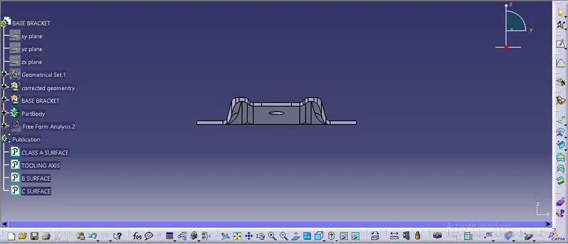
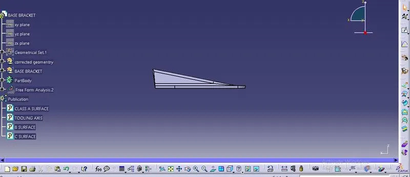
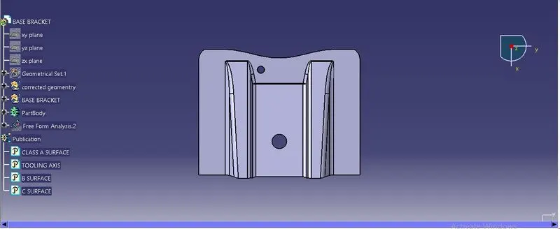
7.DIFFRENT TYPES OF VIEWS: