Week 8 - Challenge 3 - Switch Bezel Design
Creation of Thickness form class A surface
First We have to check the class a surface quality with the help of boundry option or options->display->visualization->click surface boundry check box.
Found open boundry in the surface so extact the surface & increase the merging distance to 0.003mm
Then join the surface to form a closed boundry class A surface.
Now extract the base surface to form a tooling axis & create a point in the surface, then place the axis system on to the point.
To create a Bisection create the sketch with reference to YZ plane on the point.
After that intersect the surface with reference to YZ plane & then bisecting line is created with the two line drawn on the projected line.
To create a Bisection create the sketch with reference to ZX plane on the point.
After that intersect the surface with reference to YZ plane & then create a line from reference point place at an angle of 3 degree intially (If required change the value).
By the two lines create the bisecting line(Tooling axis).To check the it clears the draft anaylsis place the tooling axis at in normal view.
Draft Analysis:
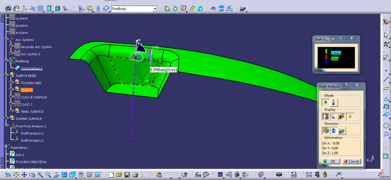
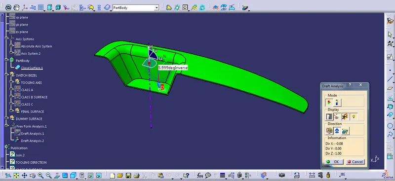
Check draft angle is 2.9 degree in color scale dialog box.
Pick the compass place it in tooling direction & lock it.
Select the surface to check draft angle(if surface satisfies the condition upper surface look green color)
Check the angle at specific with the help of analysis at running point.
Creation of class B surface:
Class B surface is created with extracting, Untrim, offset & extrapolating the surface.
After that untrim all surface to form a closed boundry.
Creation of class C Surface:
Intially multi-extract the surface outer boundry by two part.
One at curvature surface & another at straight surface to avoid error.
After extracting the two surface then create the smooth curve option to form a smooth surface.
Then sweep the curve with draft direction at 3 degree for form a surface, do the same for second boundry.
Extend the two surface to form by extrapolatr of 3mm to then trim it which will form a Class C surface.
Trim the class A, Class B, Class C to closed surface.
Then form Closed surface solid with the help of close surface option in part design.
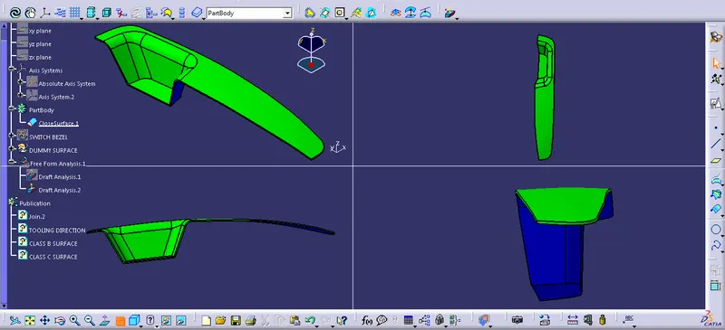
Draft analysis of solid Part.
Check draft angle is 2.9 degree in color scale dialog box.
Pick the compass place it in tooling direction & lock it.Select the surface to check draft angle(if solid satisfies the condition upper surface look green color)
Check the angle at specific with the help of analysis at running point.
Publish the Tooling Axis, Class A, Class B, Class C surface.