Week 8 - Challenge 3 - Switch Bezel Design
Objectives
To make the Switch Bezel Plastic component using the Class-A surface provided. To begin, design a tooling axis for the supplied Class-A Surface that meets the draft angle requirements, and then do a Draft analysis on the model. The Switch Bezel Plastic component's class B and C surfaces were also created. Assume that the component's thickness is 2.5 mm.
Introduction- The direction in which the mould, core, and cavity open is referred to as the tooling axis. We may perform a draft analysis of the component by giving tooling axes to it. The ejection of materials occurs after the materials are created inside the tool, therefore a draft analysis is conducted on that component.
Class A surface-The surface is made by designer and surface design is given to modeler to work on it. It is aesthetic surface and the outer most surface.
Class B Surface- A surface which is below a certain thickness from class A surface is called as class B surface. It contains engineering aspects of a model.
Class C Surface- A class C surface that join class-A and Class B surface.
Methodology- Class A surface would be provided /given by styling team.
For the model of Base Bracket Plastic component, we will follow below methodology-
- Verifying the continuity of a particular model surface, i.e., ensuring that the class A surface is properly linked or that the model is free of discontinuities. In CATIA, you may check this by utilising the Join or Boundary features.
- Tooling Axis—to determine the component's correct tooling axis.
CREATION OF TOOLING DIRECTION
- The interior trim (switch bezel) must have a nominal 3-degree draft angle when ejected from the cavity of the mould after production.
- As a result, the tooling direction is determined by taking into account the factors listed above, and the bisecting approach is employed.
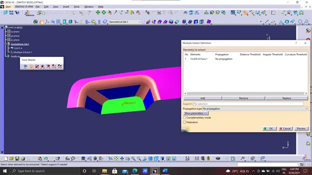
- The class - A's base surface was extracted, a point in the middle was established, and an axis system was inserted with the current feature deactivated.
- The two inclined lines were then drawn inside the positioned sketch using project intersection along the yz plane.
- Then, using the two inclined lines as a guide, bisecting lines were formed.
- The same technique is followed in the xz plane, but because there are no inclined lines on one side, the centre point is used to extrude a line along the z-axis, yielding a measurement of 5 degrees (Tentatively).
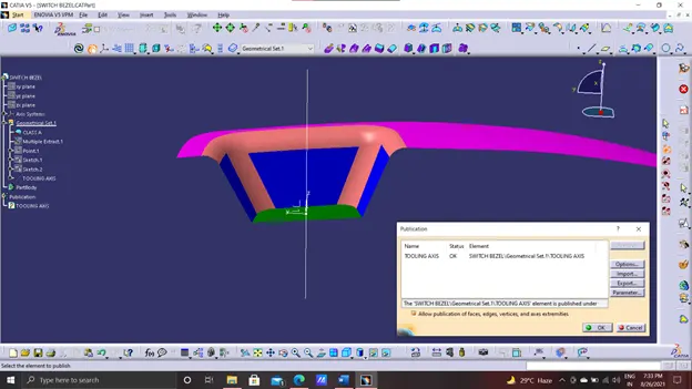
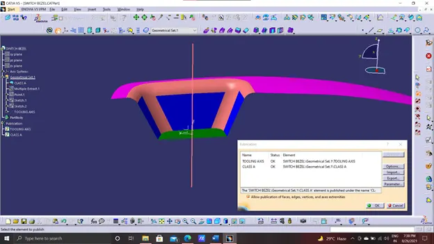
- The bisecting line is created and published using these two lines from drawings 1 and 2. (tooling direction).
- Tooling Axis
For creation of tooling axis, here we have to analyze the model carefully and focus on the surfaces which will create problem.
From below fig. we can see that blue color surfaces might create problem while tooling so we have to focus on them and create tooling axis with respective them. And in last we will bisect both X and Y direction tooling axis to get out final tooling axis in Z-direction.
- Analyzed Surfaces
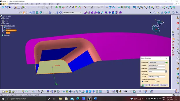
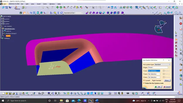
Now we will make the tooling axis in both X and Y direction of the surfaces which we thought, they might create problems. Here point is created on bottom surface and new axis system is inserted on that point.
- Point is created on bottom extracted surface
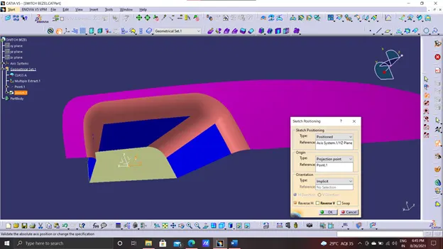
For tooling axis in Y-direction, we used position sketch on plane YZ and intersect class A surface. Now for creation of axis two lines drawn and bisect them to get tooling axis in Y-direction.
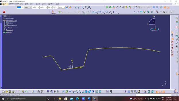
Intesection of class A suface in YZ plane. Lines are drawn on intersected class A surface. Bisect the line
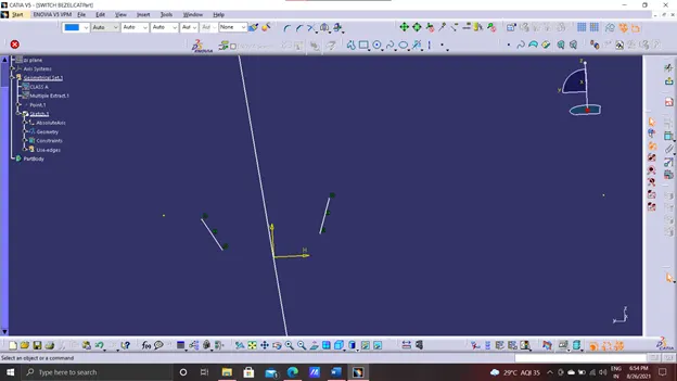
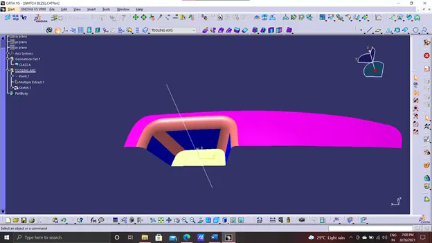
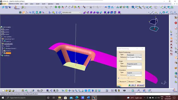
Tooling Axis Y-direction
Similarly for tooling axis in X-direction, we have used position sketch on plane ZX and class A surface is intersected.
Here only one surface is available, so line is drawn which is at angle 5 degree.
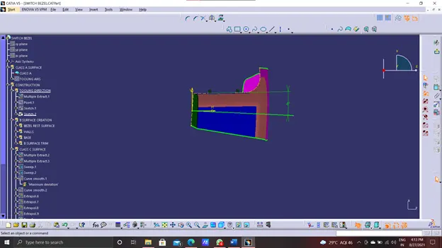
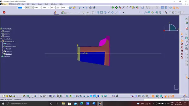
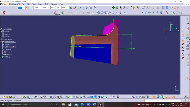
In last, we got our final tooling axis by using line bisector. We have used lines as a tooling axis in X and Y direction for line bisection purpose.
This is final tooling axis
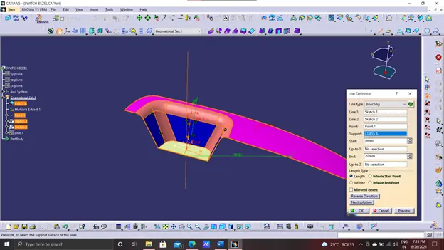
CREATION OF CLASS-B SURFACE
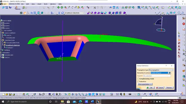
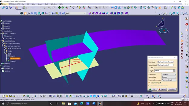
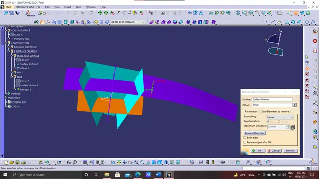
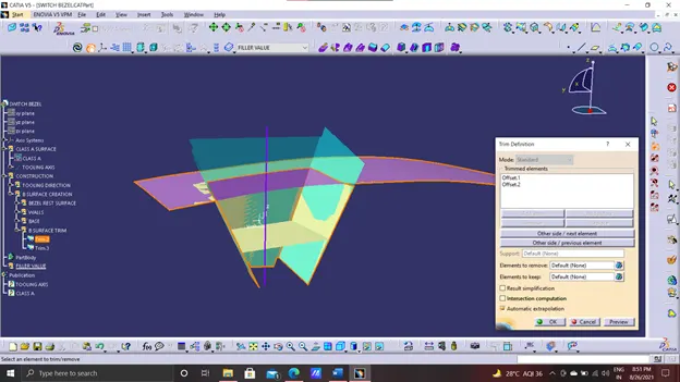
The required surface, except for the offset surface, was excised and then all of the surface was untrimmed to create the class-B surface. The intersections between all of the surfaces were then extrapolated. The B-Surface was offset to 3 mm due to the thickness of the Switch bezel, and the requisite trim procedures must be performed. Finally, the requisite corners were filled to a depth of 12.5mm (15mm-3mm). [ Fillet value of the A- surface: 15mm, component thickness: 3mm]
Top surface is extracted, then untrimmed
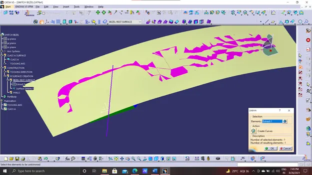
Blue color surfaces are extracted then untrimmed and extrapolated them with value one by one.
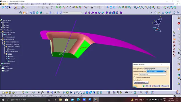
Extracted Surfaces
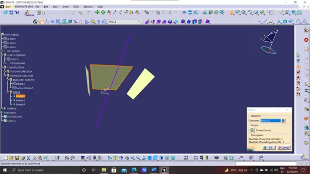
Untrimmed extracted surfaces
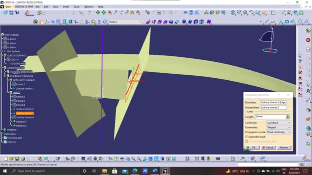
Extrapolated surfaces and Trim the extrapolated surfaces.
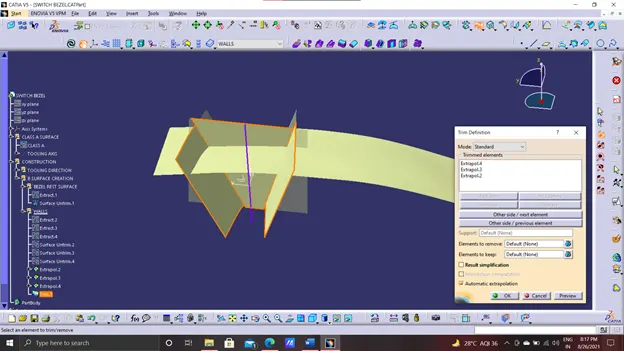
Similar procedure used here, first bottom surface is extracted and then untrimmed, extrapolated it value.
All above surfaces are at an offset of 3 mm, which is the component thickness.
Then the final trim for class B surface
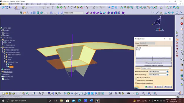
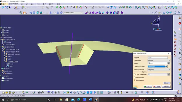
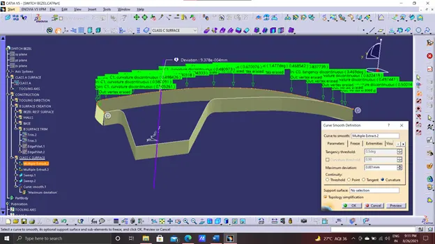
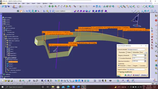
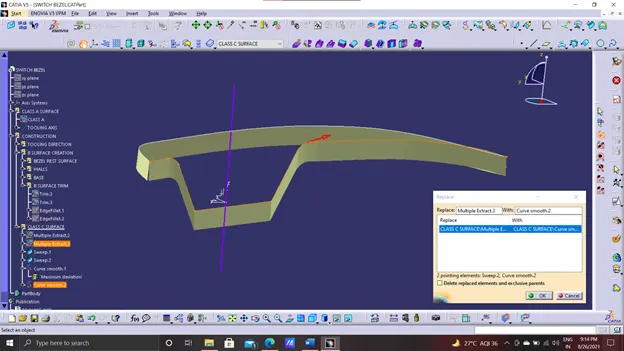
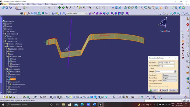
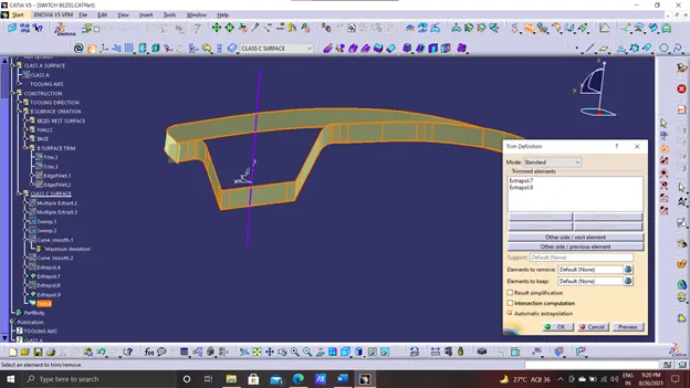
To create class C surface, extract the boundaries of class A surface in to two geometrical set name as back side wall and front side wall. Then use curve smooth feature to avoid a lot of patches and sweep the smooth curve along tooling axis.
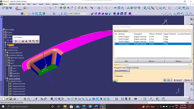
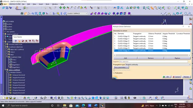
Sweep it to 3 degree.
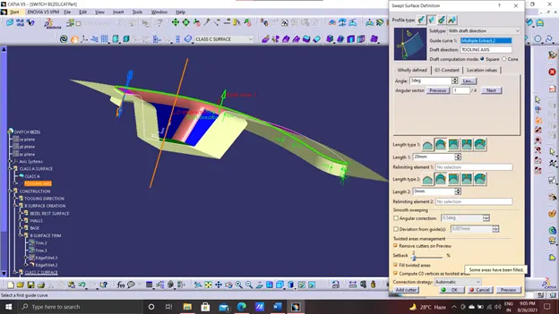
Smoothen the curve.
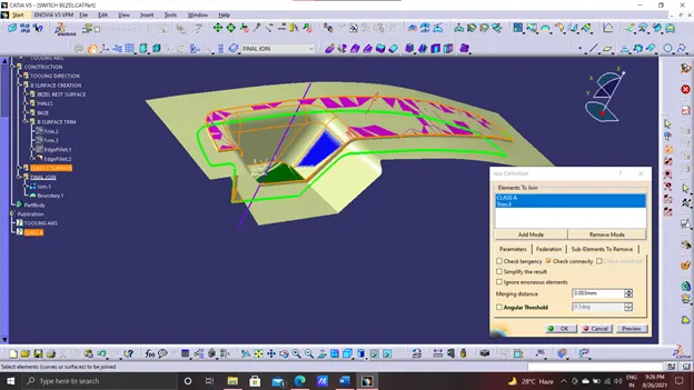
Join the class A surface and the trim.
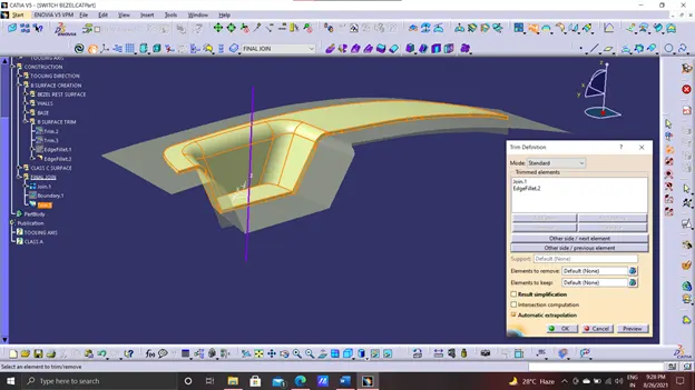
Now apply the edge fillet on the walls.
Now use solid option.
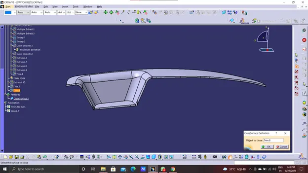
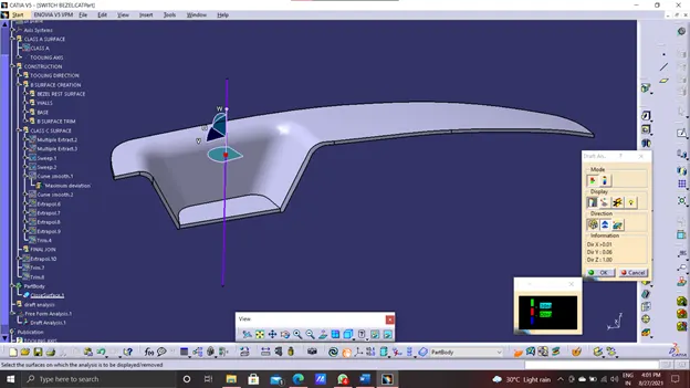
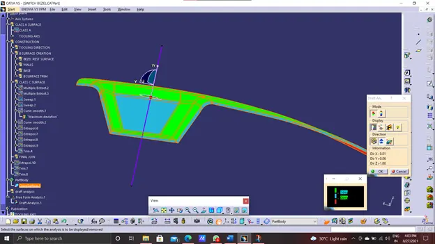
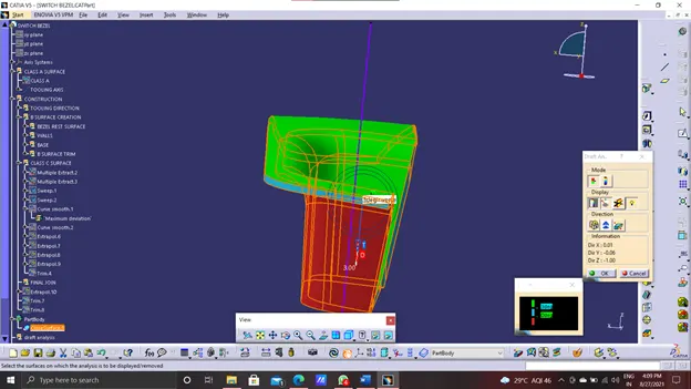
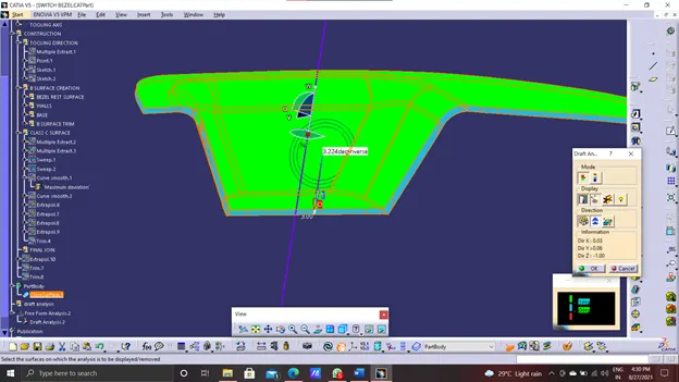
Starting with draft analysis.
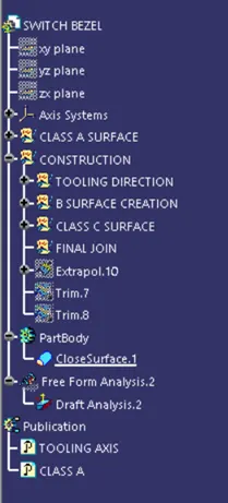
Geometrical Sets
Conclusion-
by using this challenge we learned -
- to create tooling axis
- to perform draft analysis for surface and solid body with tooling axis
- to create class B and C surface.