Week 8 - Challenge 3 - Switch Bezel Design
Switch Bezel Design (Challenge-3)
What is Generative Shape Design?
The Generative Shape Design provides an extensive set of tools for creating and modifying mechanical surfaces used in the design of complex shapes or hybrid parts, its feature-based approach offers a productive and intuitive design environment to capture and reuse design methodologies and specifications. It helps to design advanced shapes that are based on a combination of wireframe and extensive multiple surfaces which includes high-level features with full specification capture and reuse.
What is Draft Analysis?
The Draft Analysis command enables you to detect if the part of you drafted will be easily removed, this type of analysis is performed based on color images identifying zones on the analyzed element where the deviation from the draft direction at any point corresponds to specified values.
No parts can be ejected from the tool if it is having a straight 90-degree profile from its base surface, a small draft angle is provided to each and every area of the component in order to get an easy removal of the component from the tool. Draft analysis technique is used to analyze whether our part model created in cad is manufacturable based on the draft condition applied.
In the molding process the molded parts have to eject from the die so there are some issues while removing the molded parts it may get sticky with the die, or while removing the chances to get damaged, so we need to set up is the draft angle this draft angle helps the molded part to eject from the die easily.
What is Class A, Class B, Class C Surfaces?
Class-A Surface: Surfaces made by the designer which is given as an input to the plastic modeler to work on, it is aesthetic surface and the outer most surface.
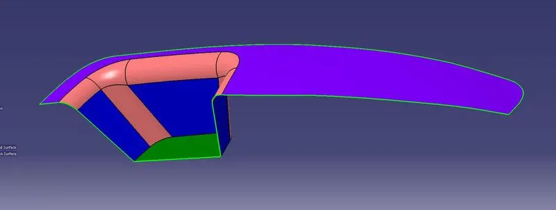
Class-B Surface: Surfaces made below a certain thickness from the Class-A surface is Class-B surface. This is the surface that contains engineering aspects of the model.
Class-C Surface: Surfaces that join Class-A and Class-B surfaces is Class-C surface.
Methodology
In this Base Bracket creation, we have the CLASS A surface given to us, so we focused on few things:
- Tooling Axis:
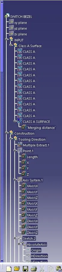
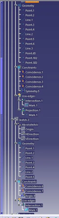
- A reference point is created along the Surface zero and new Axis System is created.
- The X Direction along the Class A and Y Direction along the Class A were used to create Tooling Direction.
- Finally, the Tooling Axis is created by bisecting the two lines and it is published. Class A surface as input using surface operation commands Class B is developed.
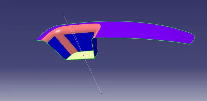
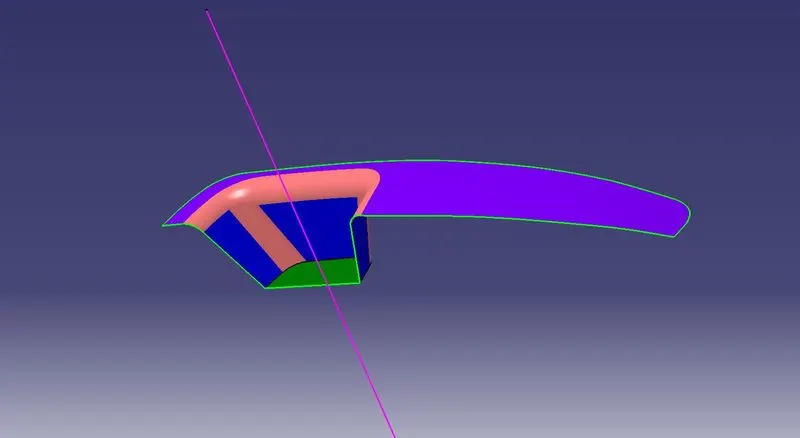
- Draft Analysis:
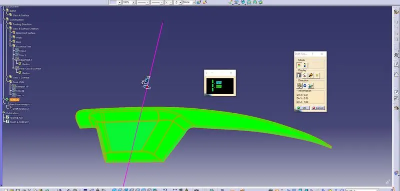
The Draft analysis for a 3 Degree draft is done on the Class A surface, so can be seen all the surfaces are more than 3 Degree of draft.
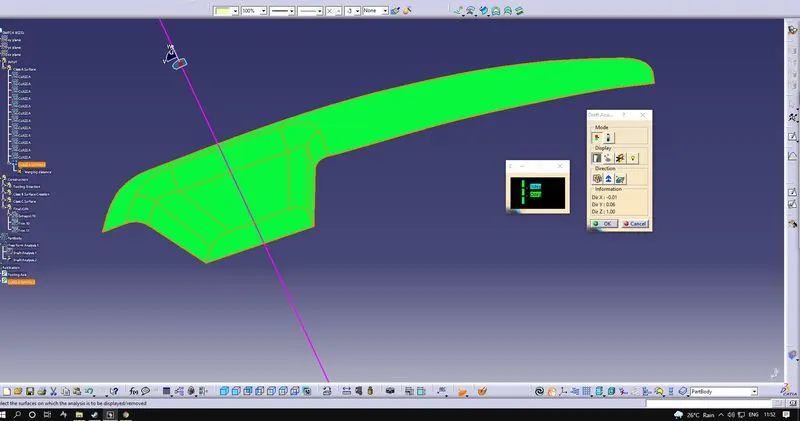
- Class-B Surface:
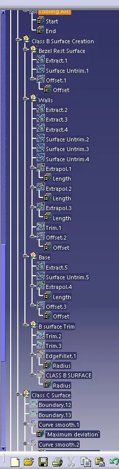
- The next step is to design B surface for the input which is usually the surface where all the engineering aspects and support creations are done.
- The B surface creation is performed using the surface operations in CATIA which is an offset from class A with dimension proportional to the thickness of the part.
- In Switch Bezel the B surface is offset 2.5mm from the Class A input which is the thickness of the part.
- The B surface is an extrapolated surface compared to A surface and forms the bottom skin of the part.
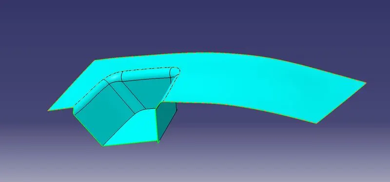
- Class-C Surface:
- The next step is to form the Class C surface which is an intermediate surface between A and B and is used to give the closed surface appearance to the design.
- The C surface is swept using the profile as boundary line of Class A which is the guide curve with a subtype along the draft direction.
- The direction of the sweep is the tooling direction formed earlier.
- The draft angle for the sweep operation is provided which is 3 degree and surface is swept for the length above the thickness of the specified part.
- The C surface is redefined using Smooth Curve tool to remove the complexity and patches along the swept surface.
- Finally, the Class A and Class C surfaces are joined together and connexity of surfaces should be less than 0.003mm and the surfaces are merged.
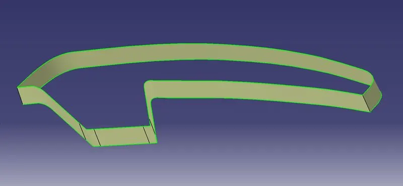
- Final Trims:
CLASS A + CLASS C:
To make sure that there is not any open boundary between class A and class C, we used join option to create a single body, this is done to make sure that parting line doesn’t lie between these two surfaces.
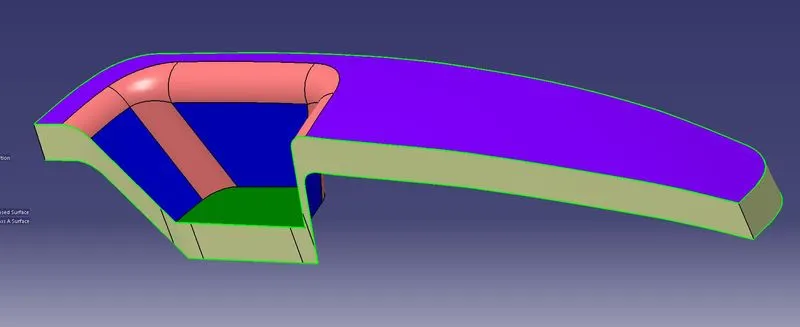
CLASS A + CLASS B + CLASS C
In this last step we have trimmed the above shown surface with the Class B surface using the trim feature.
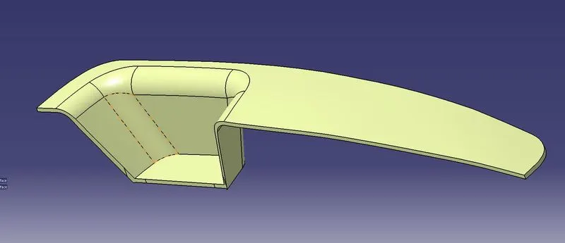
- Making a solid model from surface:
After completing the previous step, go to PART DESIGN, and use the closed surface feature to close the model.
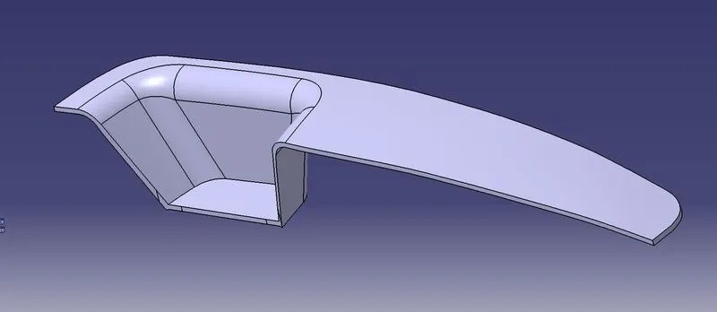
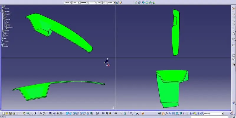
- Draft Analysis on the Final Component:
To perform Draft Analysis on the model, go to the menu bar > select insert > Analysis > Feature Draft Analysis.
To give draft direction, use the compass and align it with the tooling axis which we created for the model, once it is properly aligned, select the surfaces of the model which will show us the draft angle given on the component is having a 3 deg draft value (green color). If the draft value is negative (component showing color in red) then we need to adjust the tooling axis direction with the help of a compass.
TREE