American Chopper Using SolidWorks
American Chopper Modelling Using Solidworks
- Objective:
- The objective of this project is to create different part of models of the American chopper using Solidworks 2019.
- To create assembly of the American Chopper by the means of part models created.
- Lastly, create Rendered as well as Photorealistic images of the American Chopper
- using Solidworks Photo360 as well as Solidworks Visualize.
- What is Part Modelling?
Part Modelling is a process of creating a virtual prototype of an object or any component by modelling each individual part separately, by means of different sketch tools as well as 3D tools to help attain the required part in graphical form. This type is called as Part Modelling.
- Here Parts to be Modelled are:
- Transmission Belt
- Kick Stand
- Front Fender
- Rear Fender
- Oil Tank
- Chain
- Pedal
- Engine
- Chassis
- Front Wheel
- Rear Wheel
- Gas Tank
In this part we’ll each part model in detail below:
Transmission Belt: Transmission Belt is a part which helps to transfer power
From the engine to the gearbox.
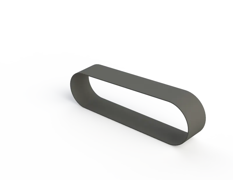
Tools used to create Transmission Belt
- Sketch
- Offset
- Extrude
- Fillet
- Appearances
Here,
- Sketch: It is 2D representation of the model with respect to the
plane/surface/view from the outside of the model.
- Offset: This tool enables you to offset a line/ shape quickly and easily from plane.
- Extrude: It is a type of tool or a feature you can say which is used to create or convert a 2D Sketch to a 3D model.
- Fillet: This is a tool that adds a highly specific arc (Fillet) between two lines/object in the drawing creating a perfect tangent arc on the end points of both sides.
Kick Stand: A kick stand is usually a piece of metal that flips down from the frame and makes the contact with the ground, when not in use it is pivoted back to the axle, it is usually located in the middle part of the chassis frame.
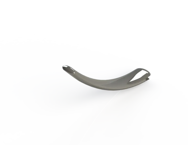
Tools used to create Kick Stand
- Sketch
- Loft
- Dome
- Extrude Boss
- Extrude Cut
- Fillet
- Split
- Appearances
Here,
- Loft: This tool is used to create complex 3D solids or surfaces formed within the spaces between various cross sections, these cross-sections can be created as sketches, faces etc, those cross-sections are called as “Loft Profiles”.
- Dome: This tool is used to create dome like curved structure be it convex or concave, it is done by selecting the face of the object where the dome is needed.
- Extrude Cut: It is same as the Extrude Boss/Base but in opposite direction it helps to Cut/Remove material from a 3D Object, it is used mostly for creating holes, channels, slots etc.
- Split: Split tool/ Split line tool is used to project any kind of entity on another surface faces, you can also split faces on multiple bodies with one command.
Front Fender: Front Fender is usually located at the front forks above the wheel to protect the chassis and the rider from mud, debris and other foreign particles.
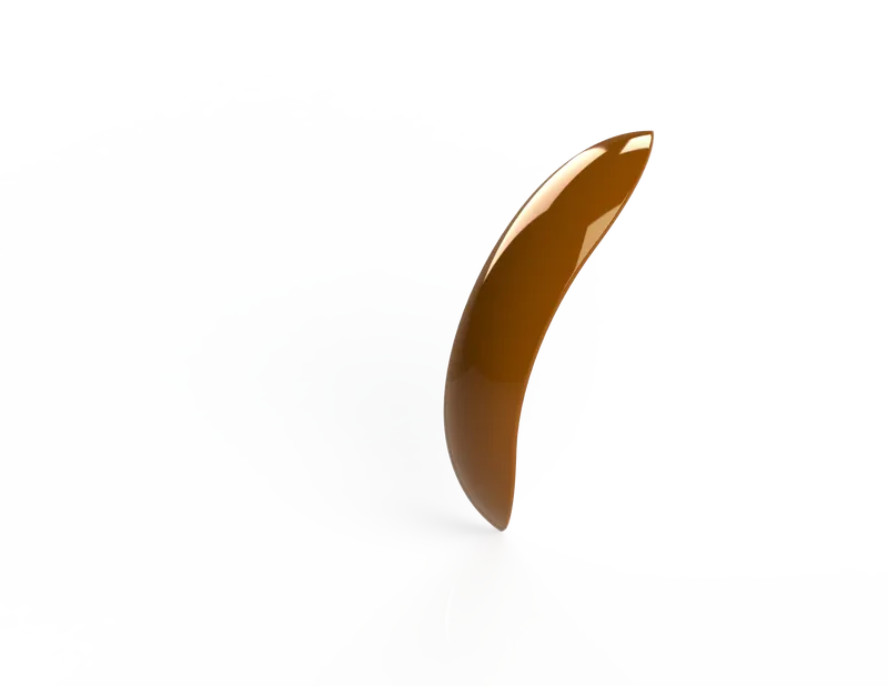
Tools used to create Front Fender
- Sketch
- Offset Entities
- Trim Entities
- Revolve
- Dynamic Mirror
- Appearances
- Split
Here,
- Trim Entities: This tool is used when you want to trim or extend a line/surface of any kind, this option is available with 2D Sketches and 3D Sketches/Planes.
- Revolve: It is a tool which creates a 3D object using the revolve tool by selecting one or more profiles and revolving them on an axis or a centreline.
- Dynamic Mirror: In this tool, its easy as it mirrors your sketch entities as you draw them, it mirrors according to the selected plane/axis/centreline etc.
Rear Fender: It is as same as the Front Fender, same objective and is located at the rear side above the rear wheel.
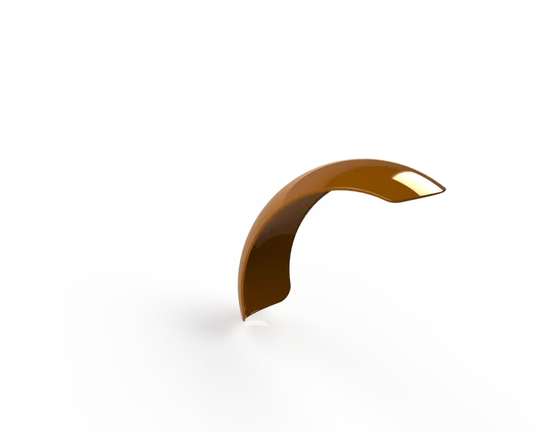
Tools used to create Rear Fender
- Sketch
- Offset Entities
- Trim Entities
- Revolve
- Appearances
Here,
- Appearances: By using this feature you can apply colour and optical properties to the entire assembly, individual part, or particular faces, including curves, fillets, or solid bodies.
Oil Tank: The oil tank is located in between the chassis behind the engine, it’s sole purpose is used to store the Oil needed by the engine to lubricate the parts inside it, the tank is hollow from inside.
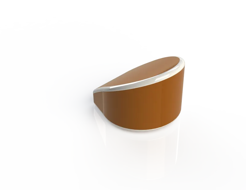
Tools used to create Oil Tank
- Sketch
- Boss Extrude
- Combine
- Fillet
- Shell
- Appearances
Here,
- Combine: This tool is used to combine to separate bodies into one whole body.
- Shell: The name says for itself it is used for creating hollow bodies with a particular thinness or thickness.
Chain: It is type of drive system used to transmitting mechanical power from one place to another, in our chopper it is used transfer power from gearbox to the rear wheel.
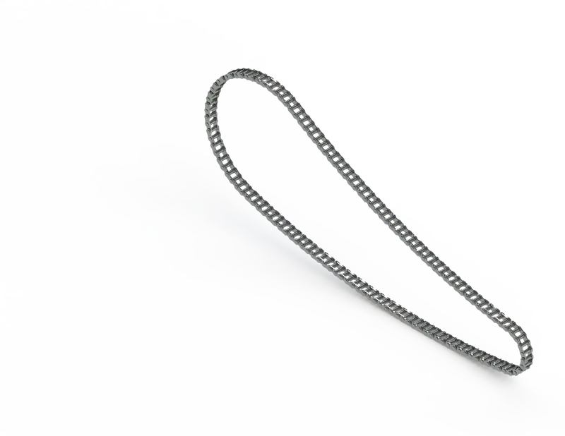
Tools used to create Chain
- Sketch
- Trim
- Fillet
- Blocks
- Extrude
- Appearances
Here,
- Blocks: You can make, save, edit, and insert blocksfor drawing items and sketch entities that you use often, such as standard notes, title blocks, label positions, and so on.
Pedal: It is connected to the chassis externally, and is used by the rider to rest his foot on while riding to attain comfort.
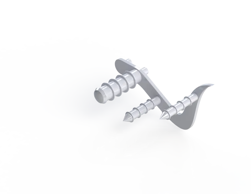
Tools used to create Pedal
- Sketch
- Extrude
- Fillet
- Linear Pattern
- Dome
- Chamfer
- Appearances
Here,
- Chamfer: The chamfer tool creates a bevelled feature on selected edges/faces/vertex. You can select types of chamfer you want as well.
- Linear Pattern: The linear pattern tool is used to create multiple instances of one or more features that you can space uniformly along one or two linear paths, to create Linear Pattern.
Front Wheel: It is a circular block that is made of alloy material known as a rim on which a tyre is mounted, a tyre is made of rubber with wires like mesh structure compressed in between them.
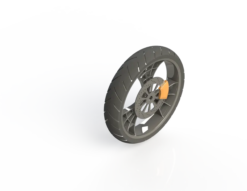
Tools used to create Front Wheel
- Sketch
- Revolve
- Trim
- Fillet Entities
- Boss/Base Extrude
- Revolve Cut
- Linear Pattern
- Chamfer
- Fillet Features
- Cut Extrude
- Circular Pattern
- Appearances
Here,
- Circular Pattern: This tool is used to create multiple instances of one or more features that you can space uniformly around an axis. This is as same as the Linear Pattern but it patterns in a circular form and on a circular axis.
Rear Wheel: It is same as the Front Wheel which is made of alloy, it is connected to the axle for ease of movement on the ground, it has a disc and sprocket. The chain is used as a drive system to connect the engine (Gearbox) to the rear wheel in the sprocket.
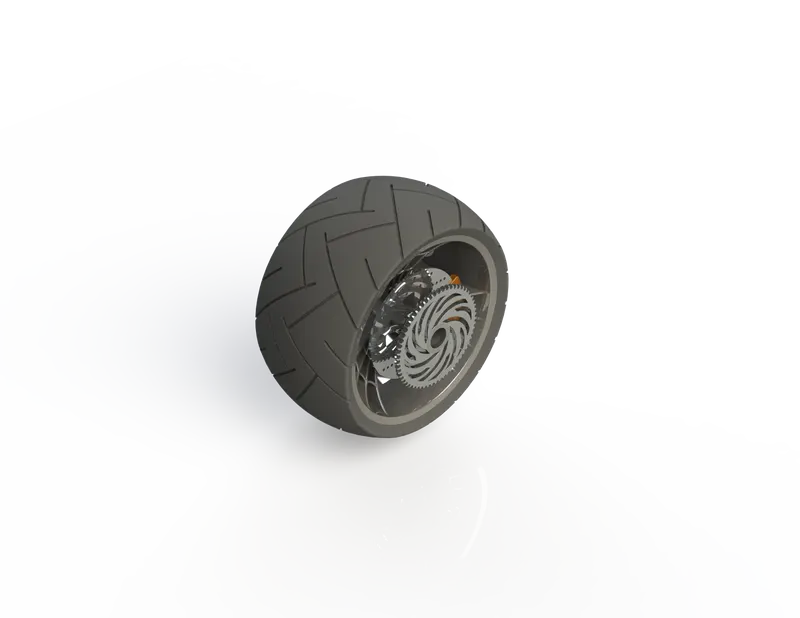
Tools used to create Rear Wheel
- Sketch
- Revolve
- Trim
- Fillet Entities
- Boss/Base Extrude
- Plane
- Revolve Cut
- Linear Pattern
- Chamfer
- Fillet Features
- Cut Extrude
- Circular Pattern
- Appearances
Front Fork: The Front Fork prevents excessive weight on the front wheel, it maintains proper damping through traction with the road surface. Front fork can be easily understood as simply large hydraulics shock absorbers.
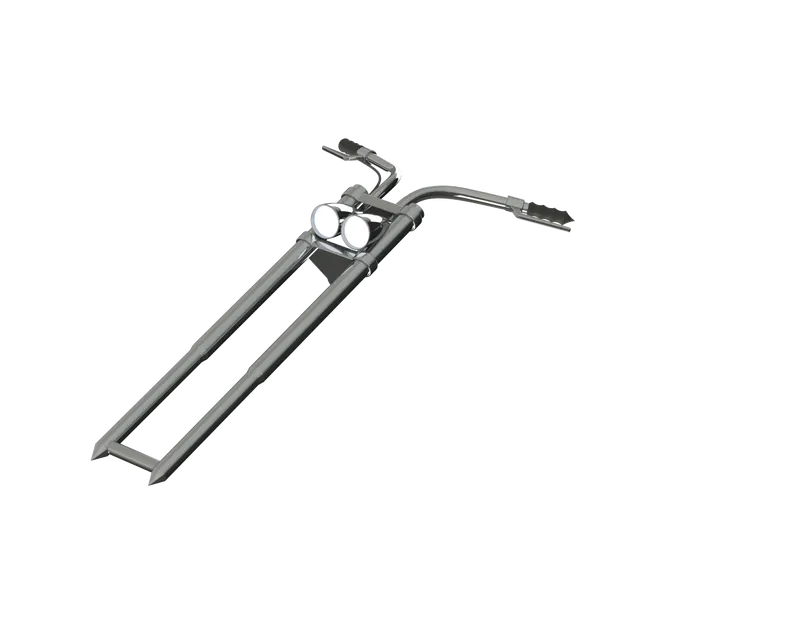
Tools used to create Front Fork
- Sketch
- Extrude
- Trim
- Revolve
- Split
- Plane
- Convert Entities
- Move/Copy Body
- Dome
- Mirror
- Combine
- Curve (Project Curve)
- Sweep
- Appearances
Here,
- Move/Copy Body: This command is an efficient way to get a model reoriented properly for a variety of downstream uses.
- Mirror: Thisis another way that SolidWorks can create a “copy” of an existing object. Additionally, you must choose a plane to mirror parts, or you’ll have to create your own plane to have the mirror performed.
- Project Curve: It is tool that can take any sketch and transfer it over to another sketch or face. You can then use that sketch for creating features to even to split a body.
- Sweep: It is a tool that creates a solid, a cut or a surface by moving a profile along a path.
Chassis: Chassis mostly referred as Skeleton, it is the most important part of the Chopper has all the other parts like rear wheel, oil tank, engine, front fork, gas tank etc. all are mounted on the chassis, skeleton structure making a rigid strength for the motorcycle.
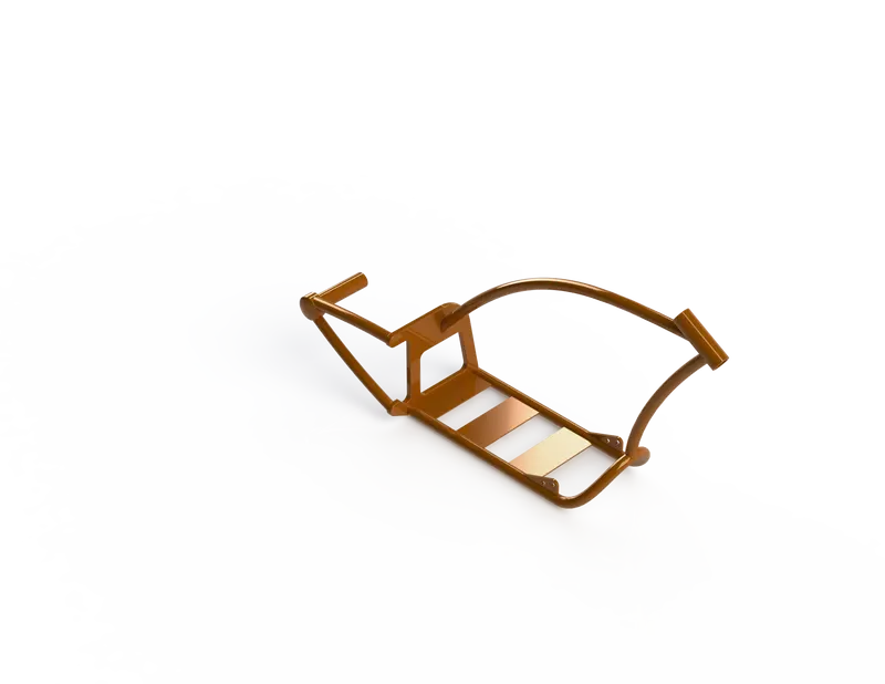
Tools used to create Chassis
- Sketch
- Offset
- Convert Entities
- Project Curve
- Trim
- Plane
- Sweep
- Split
- Revolve
- Cut Extrude
- Fillet
- Combine
- Appearances
Engine: Engine is a prime mover for the motorcycle which helps in converting any forms of energy into mechanical force as well as motion. In engine Liquid is converted to Heat energy and then the Heat energy is translated into rotational motion.
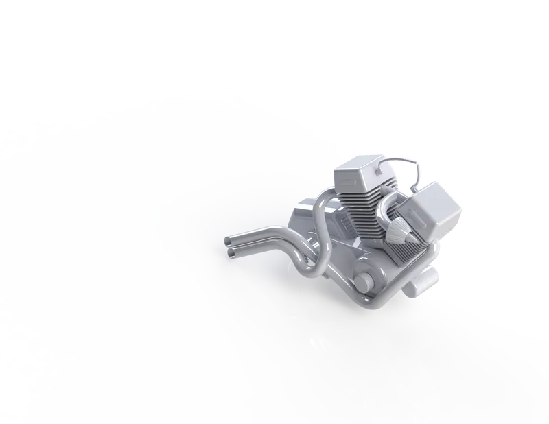
Tools used to create Engine
- Sketch
- Convert Entities
- Trim
- Revolve
- Boss Extrude
- Cut Extrude
- Offset
- Dome
- Fillet
- Project Curve
- Composite Curve
- Sweep
- Mirror
- Circular Pattern
- Split
- Planes
Gas Tank: The name itself says the purpose of it, it is used to store gasoline/petrol/gas many names can be given to it, the gas tank is hollow from inside and send the fuel to engine by various form (Fuel Injection) in the required quantity and whenever required.
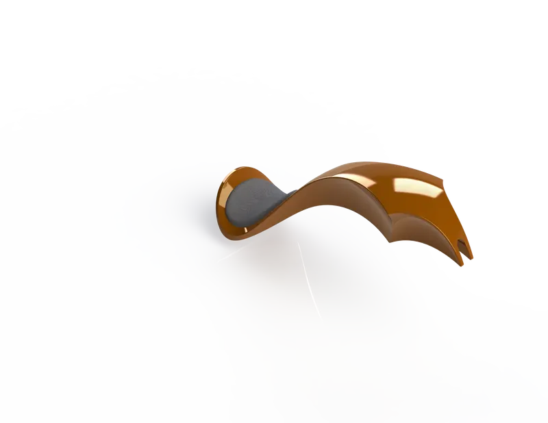
Tools used to create Gas Tank
- Sketch
- Trim
- Project Curve
- Convert Entities
- Sweep Surface
- Loft Surface
- Fill Surface
- Surface Trim
- Surface Knit
- Sweep Cut
- Fillet
- Appearances
Here,
- Loft Surface: This feature creates a shape by making transitions between multiple profiles and guide curves. This tool is very valuable for modelling complex surfaces.
- Sweep Surfaces: These are created from the previously generated section curve positioned along the path.
- Filled Surfaces: The Filled Surfacefeature constructs a surface patch with any number of sides, you can use this feature to construct a surface to fill a gap in a model.
- Surface Trim: You can use a surface, plane, or sketch as a trimtool to trim intersecting surfaces.
- Surface Knit: Use the Knit Surfacetool to combine two or more faces and surfaces into one, the surfaces do not need to be on the same plane.
Assembly of Chopper:
- Firstly, all the parts brought under one roof using the normal open and select all the parts together
- Secondly, the chassis is inserted into the assembly window using the Insert Part tool, same is done for the parts as well.
- Lastly, each and every part is connected to the desired another part using the tool Mates and fix to their respective location.
Tools used to create Assembly of Chopper
- Insert Part
- Mates
Here,
- Mates: It create geometric relationships between assembly components. As you add mates, you define the allowable directions of linear or rotational motion of the components. You can move a component within its degrees of freedom, visualizing the assembly's behaviour.
Photo Realistic Rendering:
- Photorealistic rendering is a type of 3D rendering where the final result is very difficult to distinguish from reality.
- Photorealistic Rendering in SolidWorks can be done two ways: -
- PhotoView 360
- SolidWorks Visualize
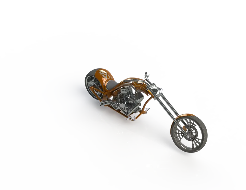
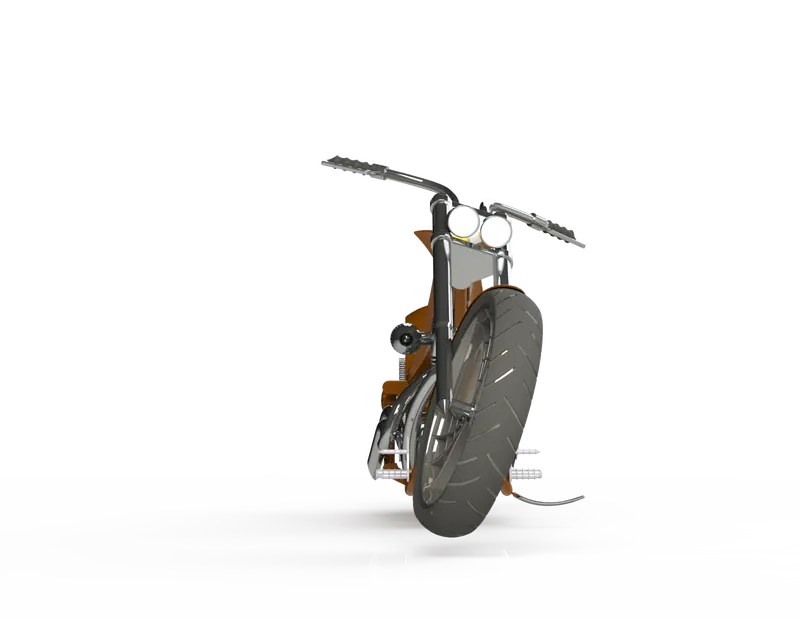
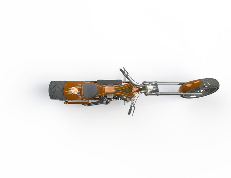
- The Following are the images of Assembly of American Chopper
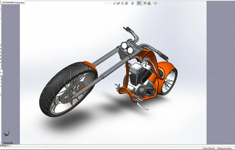
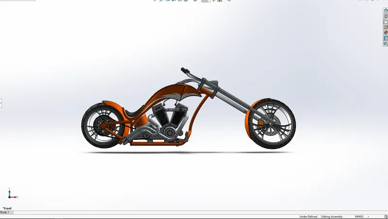
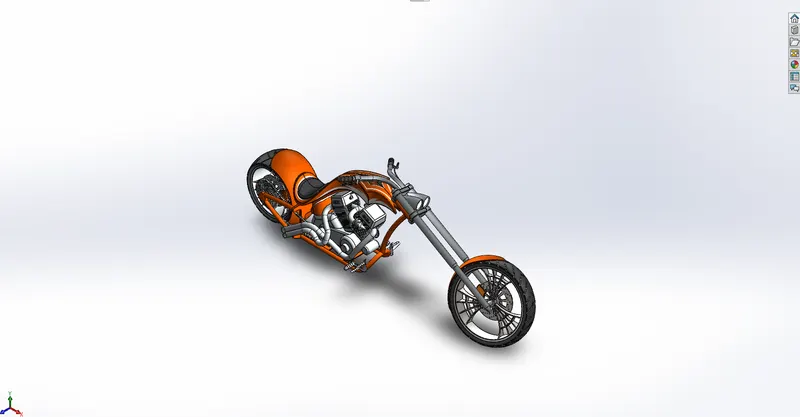
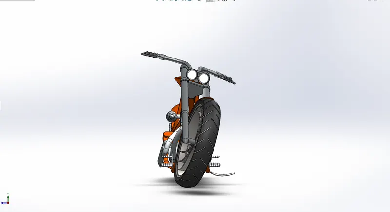
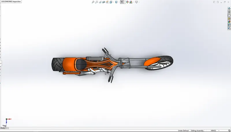
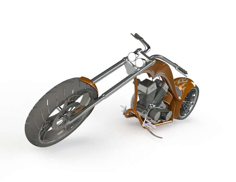
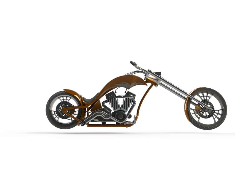
- Detailed Rendered Images of Assembly of American Chopper
- Conclusion:
- This report conclude that the parts of the American Chopper are created using various Solidworks Tools and Features in Solidworks.
- The same parts are later taken into a single environment and created as a whole assembly with the help of mates.
And lastly, the assembly was then rendered into high definition images using PhotoView 360 and an external software SOLIDWORKS VISUALIZE as well.