Advanced Sheet Metal Design Using NX Cad Challenge_2_Box Assembly
Advanced Sheet Metal Design Using NXCAD (Challenge 2 Box Assembly)
Objective:
This challenge aims to create a “Box Assembly” using different types of tools/features.
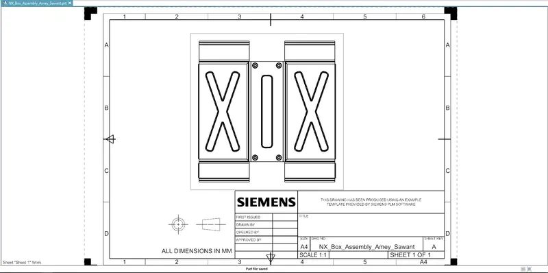
Later creating a detailed drawing sheet of it as well.
What is NX CAD?
NX CAD is an advanced high-end CAD/CAM/CAE software used for designing models etc. It was formerly known as Unigraphics owned by Siemens PLM Software.
What is Sheet Metal?
Sheet metal is a thin and flat piece of metal formed by rolling or hammering, sheets are available in many different metals, namely aluminum, copper, brass, steel, gold, silver, etc.
Tools used to create the Casing:
- Sketch
- Tab
- Flange
- Closed Corner
- Hem Flange
- Mirror Body
- Unite
- Dimple
- Mirror Feature
- Unbend
- Rebend
- Bead
- Datum Plane
- Break Corner
- Normal Cutout
- Flat Pattern
Here,
- Closed Corner: This command is used to close two adjacent flange corners in the sheet metal application.
- Hem Flange: This command is used to modify the model by folding the edges of the sheet metal flange over onto itself for safe handling or to increase the edge stiffness.
- Tab: This command is used to create a base feature by extruding the sketch along a vector by a thickness value, or by adding material to existing faces and bend regions of sheet metal.
- Flange: This command is used to create an extended part (bend) of the sheet metal, it is created on on edge of the model, the angle, length, width of the flange can be changed according to the determined requirements.
- Sketch: This command is used to sketch the required shape design.
- Bend: This command is to create bends at the required location as per your needs, the bends are fully changeable.
- Normal Cutout: This command is used to create a cutout by projecting a sketch upon the model and then cutting perpendicular to its face by the projection.
- Unbend: This command is used to unbend the whole model into a flattened sheet.
- Dimple: The dimple feature is used to strengthen the sheet metal, which is done by creating a lifting feature of a particular sketch onto the surface.
- Mirror Body: This command is used to mirror the entire body or the model across the datum plane.
- Mirror Feature: This command is used to copy and paste the features on the model by mirroring them through a plane or surface.
- Unite: This command is used to combine two or more solid bodies into one single target body.
- Datum Plane: It is known as the planar reference feature, it can be relative or fixed.
- Bead: The bead command is used to create a long-drawn-out impression which is impressed to increase stiffness in Sheet metal.
- Rebend: This command is used to rebend all the joints as previously stated to finally complete the sheet metal model.
- Break Corner: This command is used to round the edges of the Tab or flanges, it can also be called a fillet command.
- Flat Pattern: This command is used to flat the model or sheet metal design into a flattened shape to be used in drafting.
Design Methodology
- Sketch the Shape
- Create Tab
- Create Flanges
- Give them the Closed Corners
- Create Flanges
- Create HEM Flanges
- Mirror the Body
- Unite it Completely
- Sketch the Shape
- Create a Dimple
- Mirror Feature
- Sketch the Shape
- Add Dimple
- Unbend
- Rebend
- Draw the Sketch
- Add Bead
- Apply Mirror Feature
- Add HEM Flange
- Create a new Datum Plane
- Create the Required Sketch
- Create Tab
- Add Flange
- Create Sketch
- Again Add a Tab
- Apply Break Corner
- Add Flange
- Add HEM Flange
- Unbend
- Draw the Sketch
- Create Normal Cutout
- Rebend the Model
- Mirror the Body
- Create Sketch
- Add Tab
- Add Flange
- Add HEM Flange
- Unbend the Sheet Metal
- Create New Sketch
- Give it Normal Cutout Feature
- Rebend
- Lastly, Create the Flat Pattern
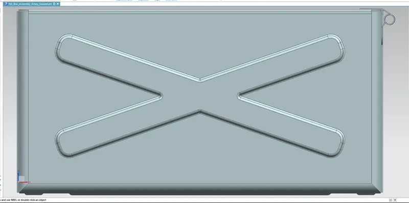
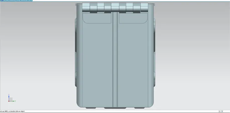
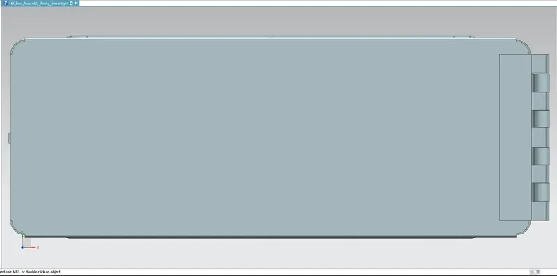
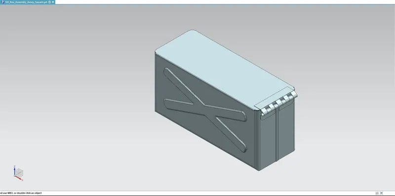
Below are the images of Box Assembly
FRONT VIEW
SIDE VIEW
TOP VIEW
ISOMETRIC VIEW
Detailed Drawing Sheet
Conclusion:
- This report concludes that the “Box Assembly” is created by using various tools/features mentioned above by using the NX CAD software.
- And a detailed drawing sheet has been attached to the report as well.