Week 8 - Challenge 3 - Switch Bezel Design
Designing a Switch bezel:
Objectives:
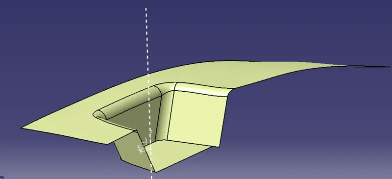
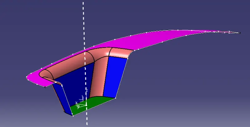
a) To create Class-B and Class-C surface from given A-surface of a switch bezel and create a solid body.
b) To perform draft analysis on Class-A surface and complete body.
For creating surfaces and performing draft analysis we need a tooling axis. Here it is done by bisecting and sketch method.
Tooling axis:
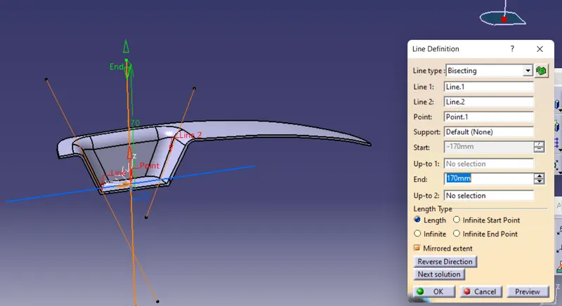
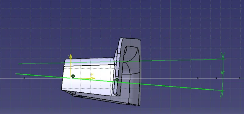
A uniform surface is created by combining all patches using 'Join' command. A point is marked at the centre of the plane in the depression of the Class-A surface. An axis system is then set with the point as the origin. The Z-X plane and Z-Y are intersected with the body to form the curves of intersections. Tooling in Y-direction is created with by bisecting method using the bisecting command option under line command. Tooling in X-direction is created by inclining a line 6 degrees from the intersection line.
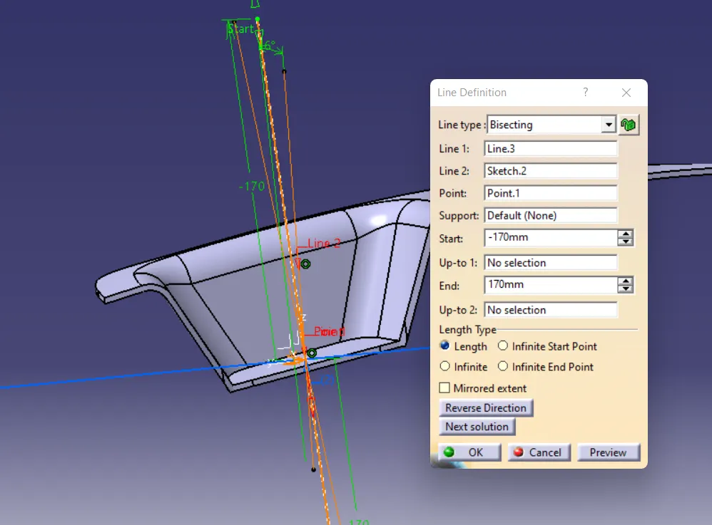
Final tooling axis is created by bisecting the toolings in X and Y directions.
Tooling in Y:
Tooling in X:
Final tooling axis:
Class-B surface creation:
The procedure for creating Class-B is as follows:
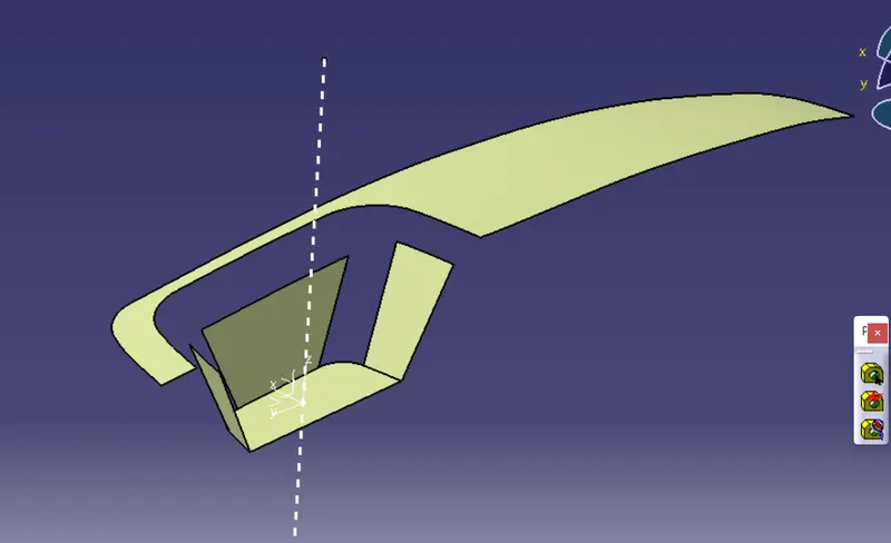
a) Extract the surfaces that are planar without fillets.
b) Offset all of them to a distance of 2.5mm.
c) Untrim each of them and extrapolate until required.
d) Having all the extrapolated surfaces, trim all of them collectively to get the required shape.
e) Give fillets to edges as required. Inner fillet radius = Original fillet radius - Thickness of the component.
Extraction:
Offset:
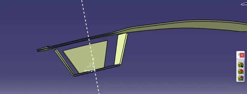
Untrim:
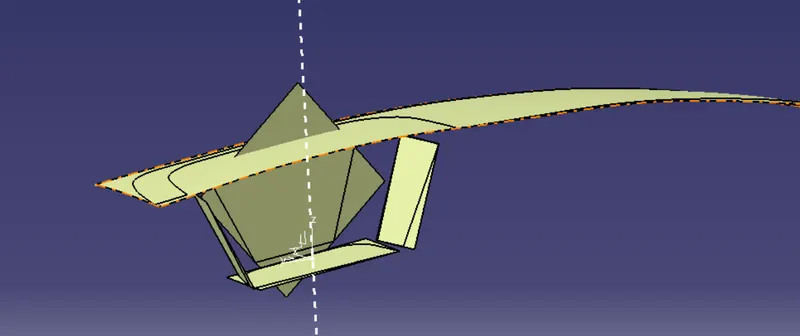
Extrapolation:
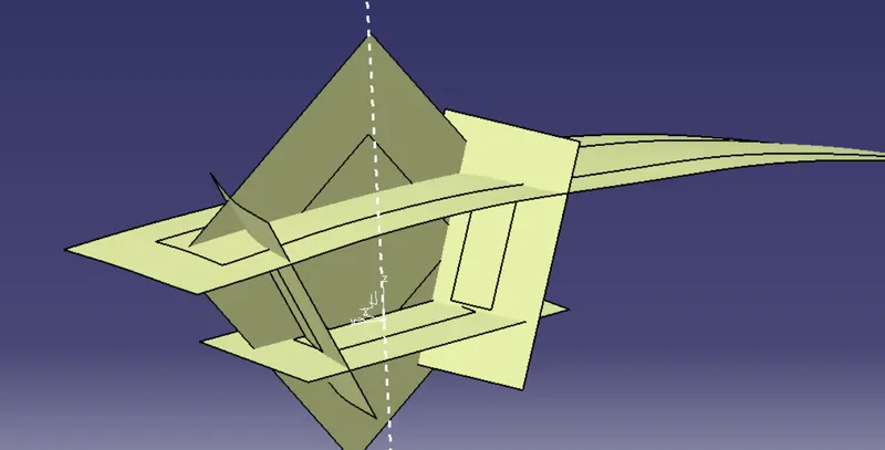
Trim:
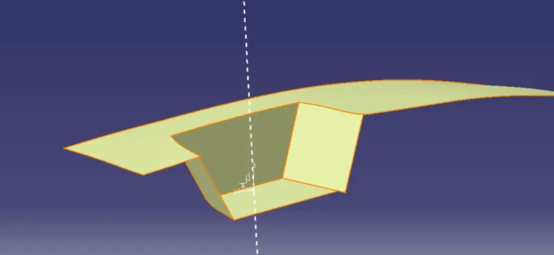
Class-B:
Class-C surface creation:
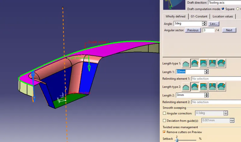
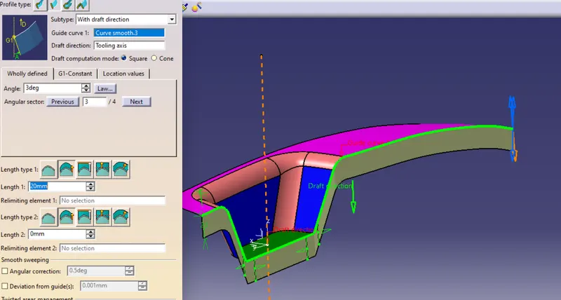
Sweep command is used to create Class-C surface.
a) Extract the outer boundary of A-surface seperately in two parts.
b) Select the 'Draft direction' option under the sweep command.
c) Give the extracted bondary as the reference curve and tooling axis as the draft direction.
d) Ensure the direction of sweep to be extending outer.
Extrapolate the two halves of the surfaces obtained and trim them to get the final C-surface.
Join A and C surfaces. Trim the unit with B-surface to form a complete closed surface.
Make sure that the surface has no open boundaries. A solid body is formed with closed body command.
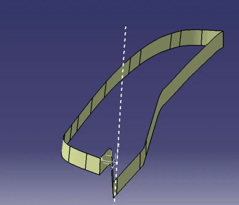
Final Surface:
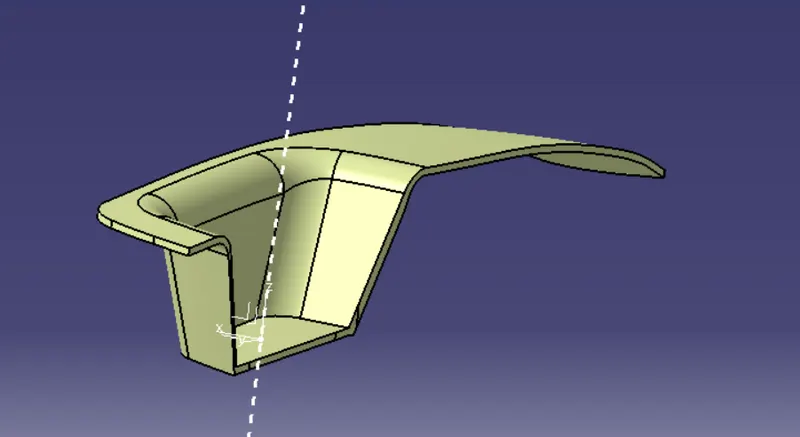
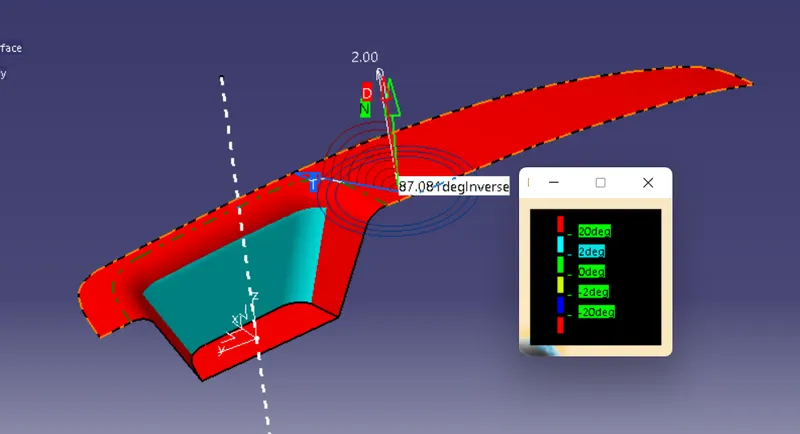
Draft analysis:
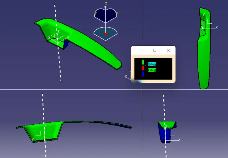
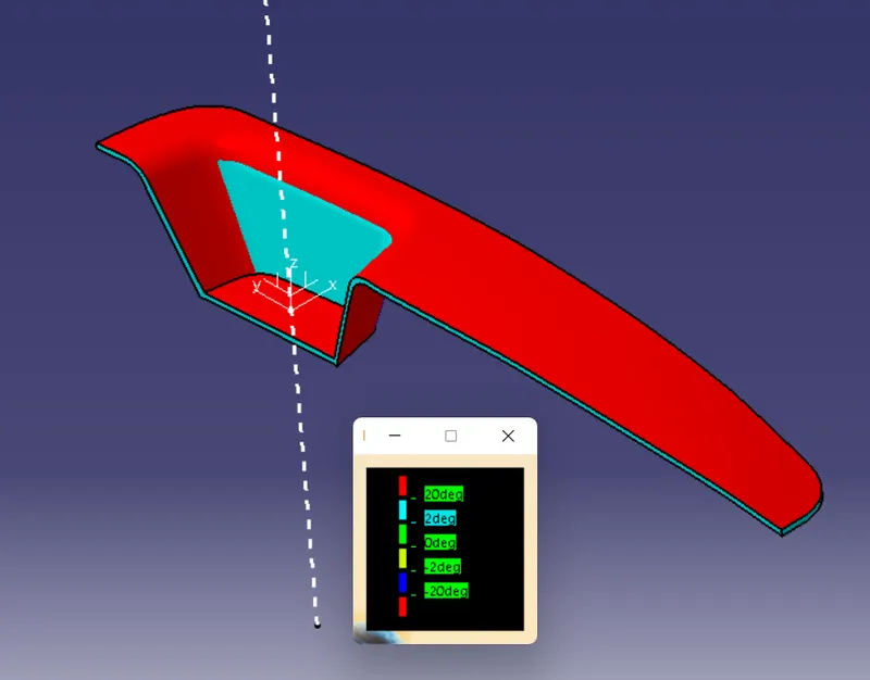
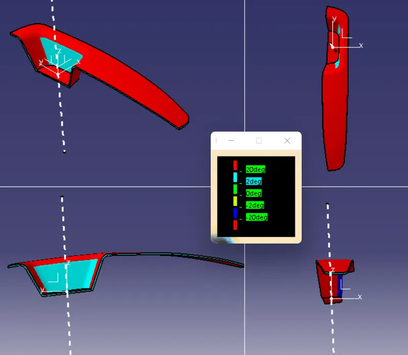
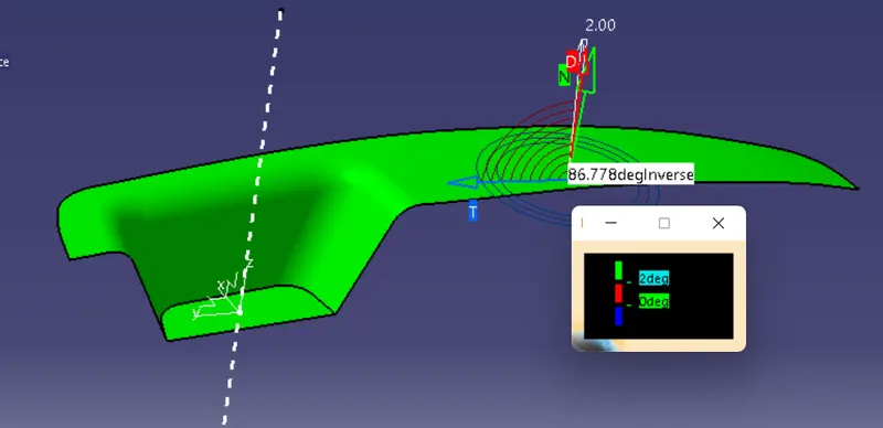
Draft analysis is used to analyze the angle of inclination of various portions of surface or body from the tooling axis. This is done through the following steps.
a) Keep the 'Materials' option active in 'Customization view' command.
b) Select 'Feature draft analysis' under analysis option.
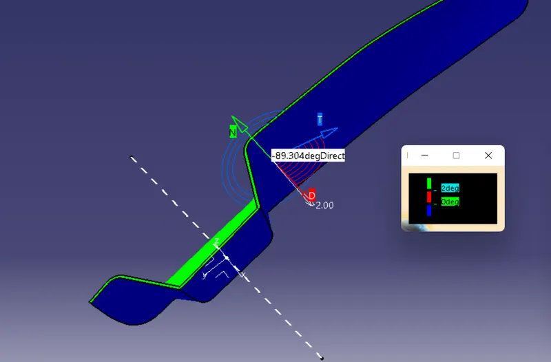
c) Draft analysis window is displayed. Click on the Compass button and orient it in the tooling axis direction.
d) Lock the orientation and click on any portion of surface/body to get compelete analysis.
Draft analysis of Class-A surface:
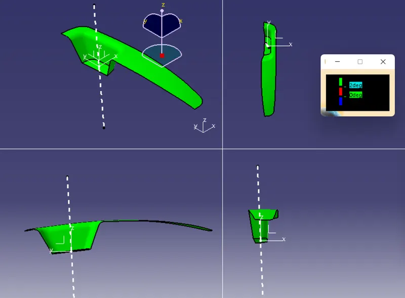
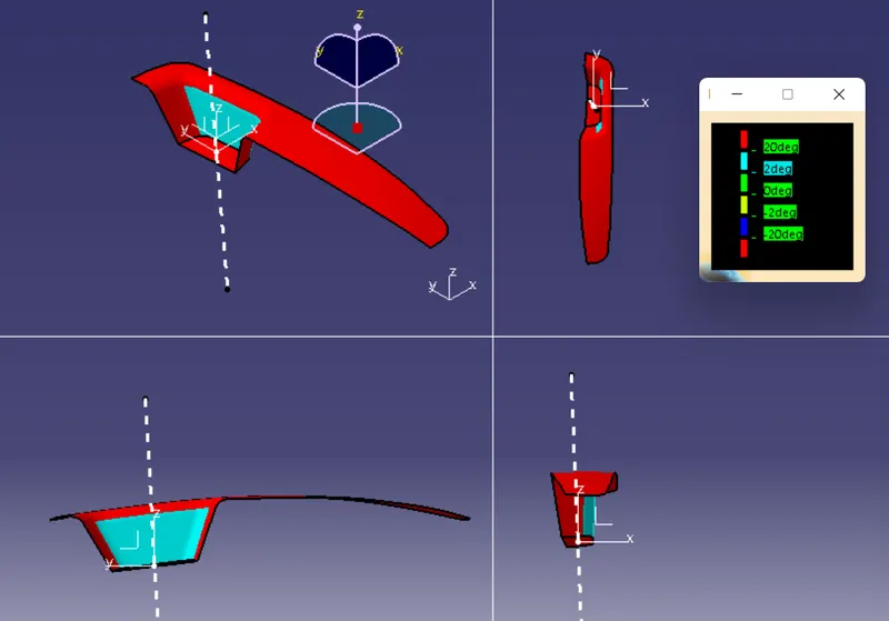
Draft analysis of Complete body: