Week 8 - Challenge 2 - Base Bracket Design
DESIGNING A BASE BRACKET
Objectives:
a) To create class-B, class-C surfaces from given class-A surface of a base bracket.
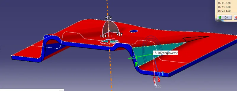
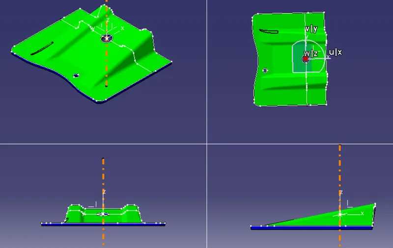
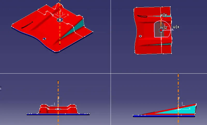
b) Perfrom draft analysis on the planar class-A surface as well as the entire body of base bracket.
Intoduction:
Class-A surfaces are responsible for the aesthetic look and good customer experience for a particular product. Class-B surface serves as a base to hold various engineering components related to a particular product, positioned parallel to the A-surface. Class-C surface bridges both A,B surfaces forming a compelete body.
Before creating these surfaces the continuity in the given surface is checked and a tooling axis is created.
All the surfaces are joined into a single one by Join command.
Tooling axis creation:
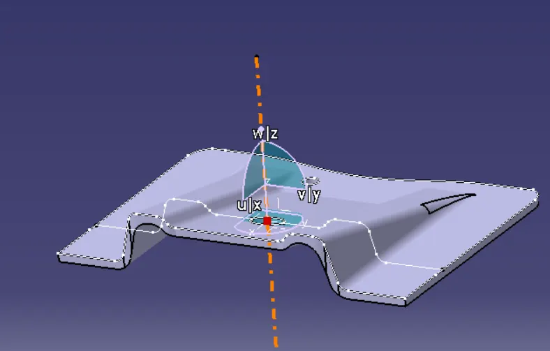
A boundary is defined on the surface. Mark the centre of the circle at the top of the base bracket surface. For creating a tooling axis, an axis system is defined with the point as a reference.
Intersect the Y-Z plane in the axis system with the surface to get appropriate profile in the plane as shown below.
The lines are formed by 2-point command from two inclined lines as shown below. The tooling in Y-direction is formed by bisecting these two lines.
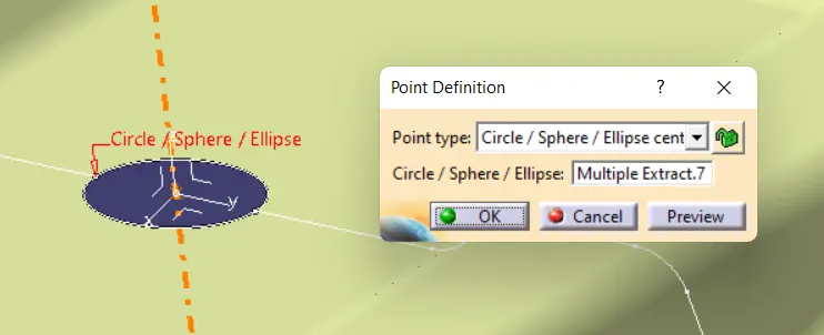
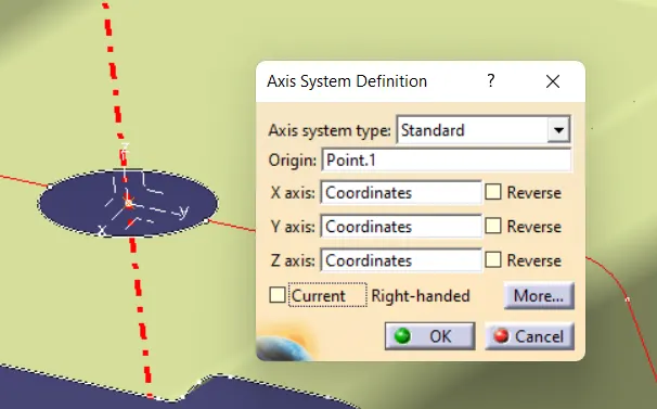
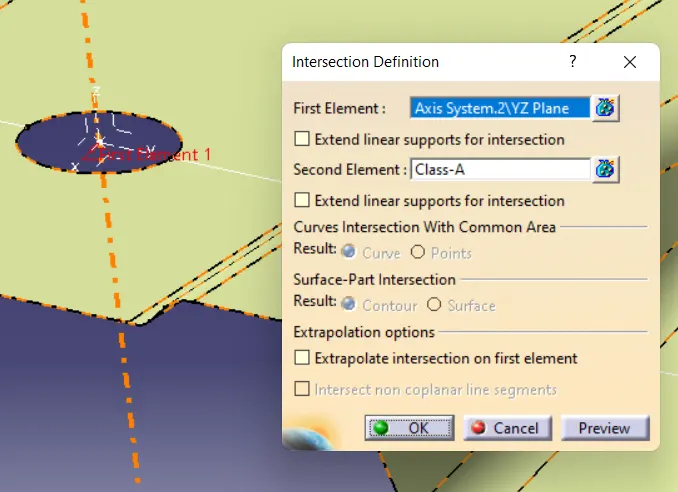
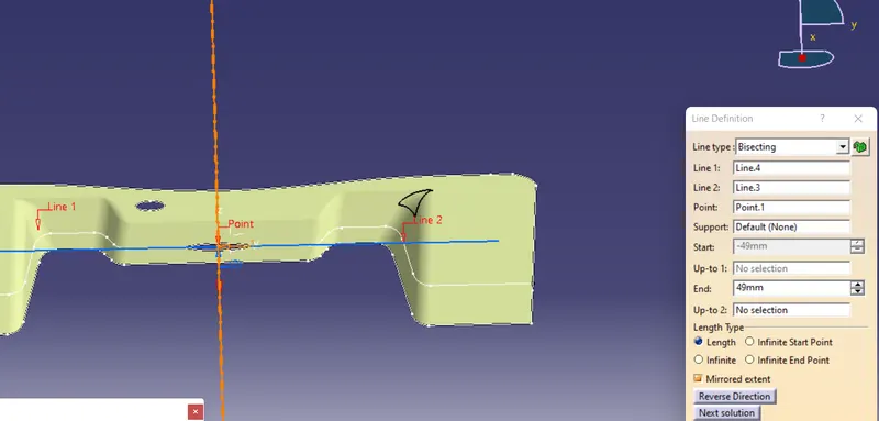
Class-B surface creation:
This is done through the following steps:
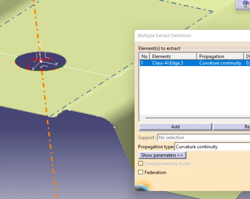
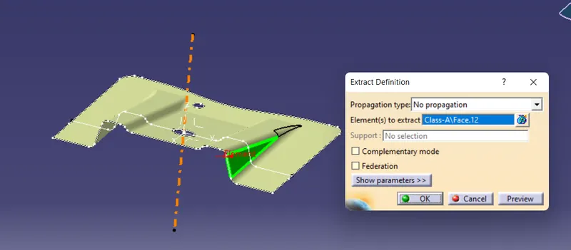
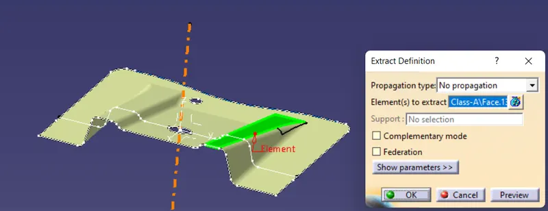
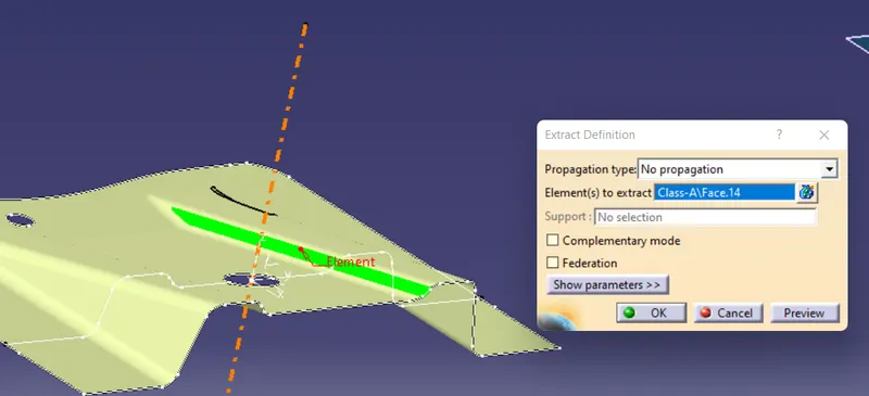
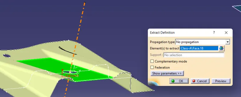
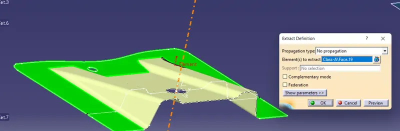
1) Some planar surfaces without curvature are extracted.
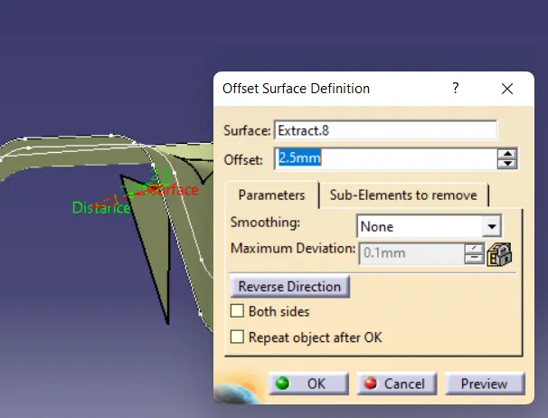
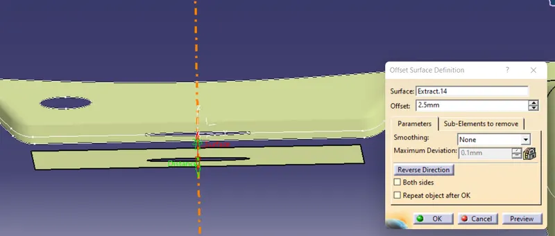
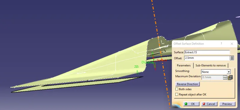
2) The extracted surfaces are untrimmed and offsetted to a distance of 3mm.
3) All the offsetted surfaces are then trimmed according to the shape and are given proper fillets.
Extraction:
Offset:
Trim:
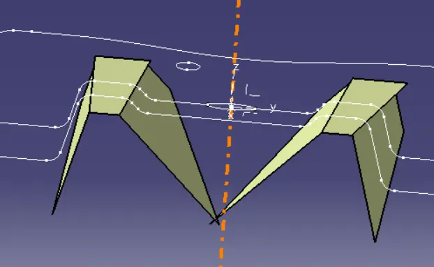
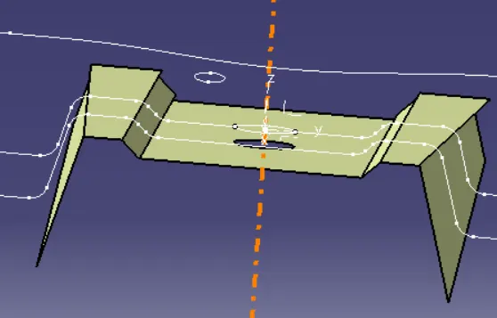
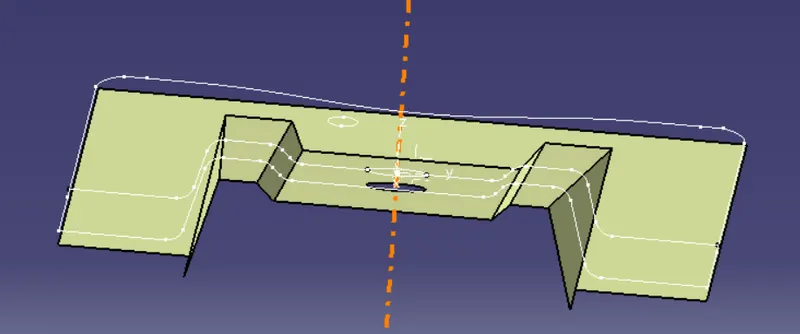
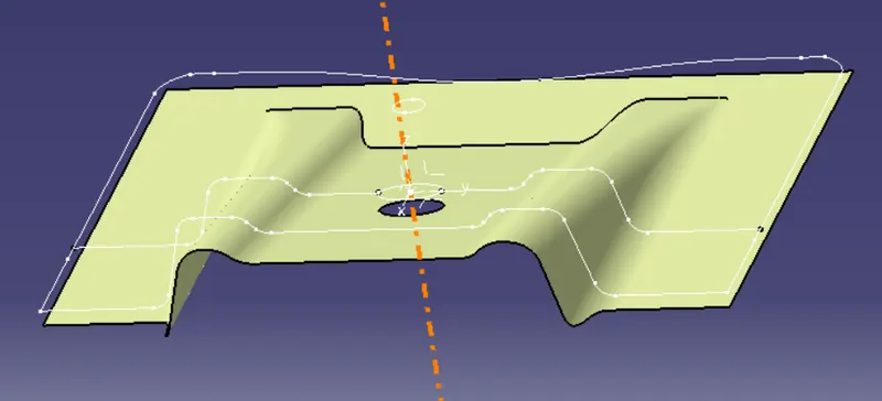
Class-C surface creation:
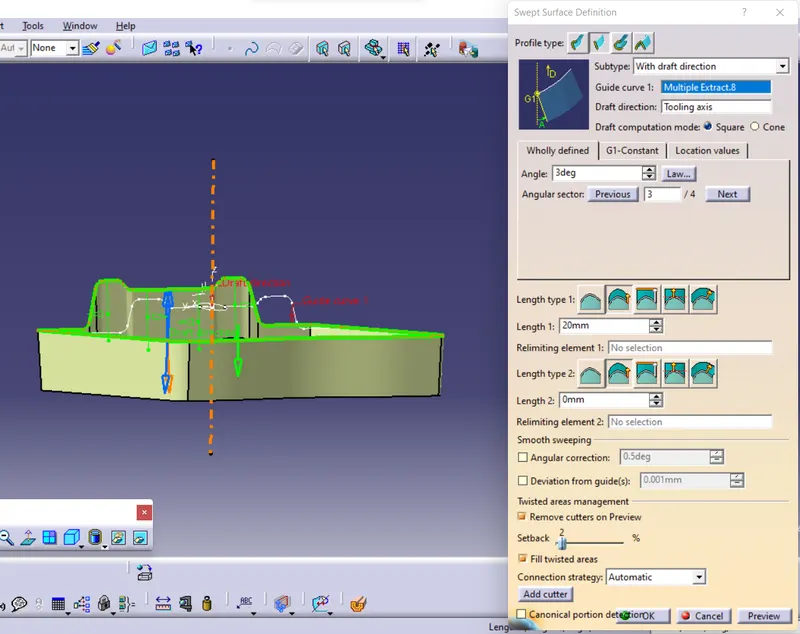
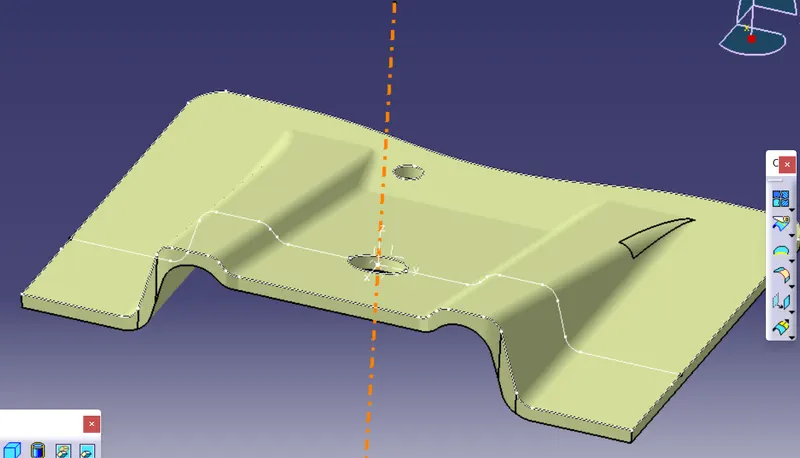
The outer boundary of the surface and that of holes are extracted. These are then sweeped using the draft option. An angle of 3 degree is given with the direction pointed inside.
 d
d
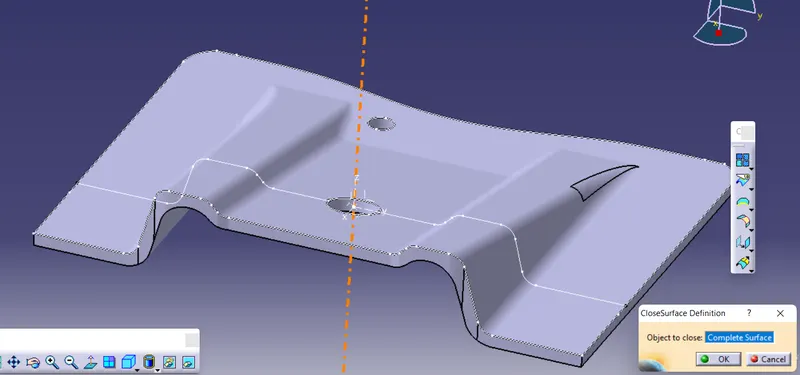
The A and C-surfaces are joined into a single one. This unit is trimmed with the B-surface to form an entire object containing A,B.C surfaces. This object is converted to a solid one using close surface command under surface options in the part workbench.
Draft analysis:
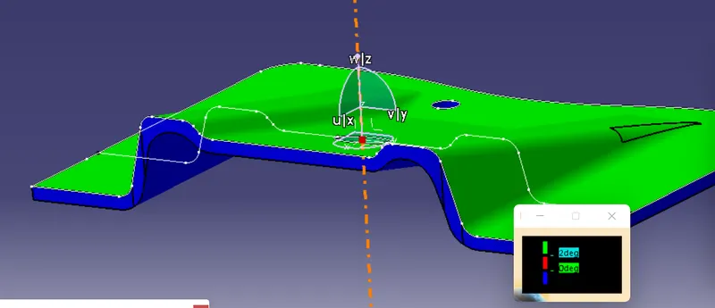
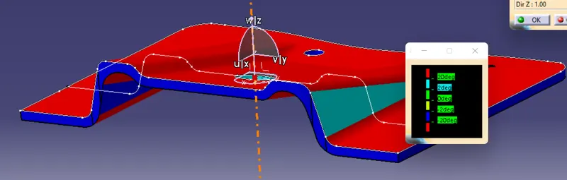
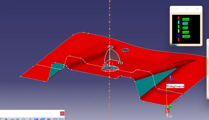
For any surface or object draft analysis is done by:
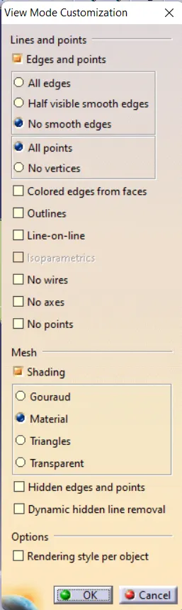
a) Selecting the materials option in the view mode customization command.
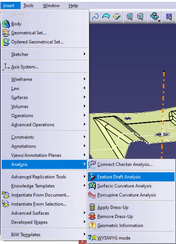
b) The 'Feature draft analysis' is selected under the analysis toolbar.
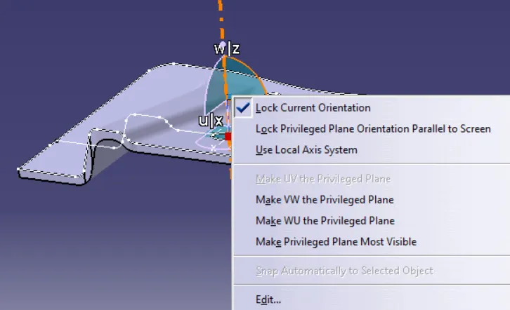
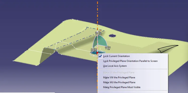
c) The object or the surface is then given a compass which has to be aligned in the direction of tooling axis.
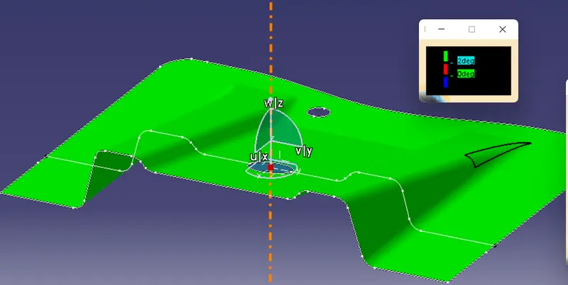
d) After locking the orientation of the compass, click on any point of surface or object to get a coloured view of the angles at different points.
e) The value of a draft at a particular point can also be seen using draft at a point command.
For Class-A surface:
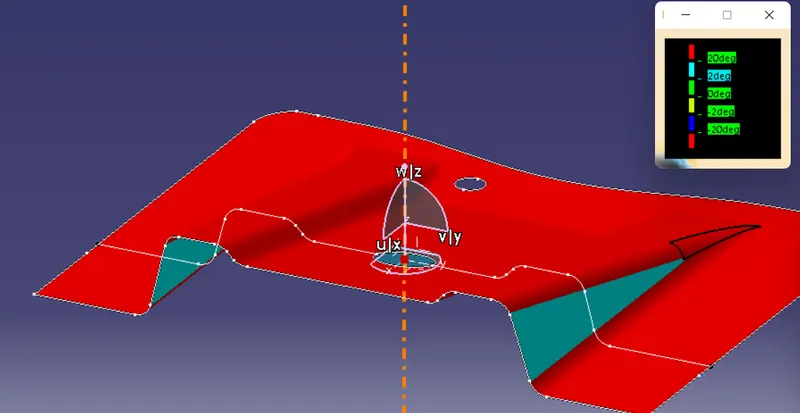
For the solid object: