Door Arm Rest Week 8 Challenge
Design and Draft analysis of a door arm rest:
Objectives:
a) Generate B and C surfaces from given A-surface of door arm rest.
b) Perfrom draft analysis on Class-A surface and final body.
Class-A surface:
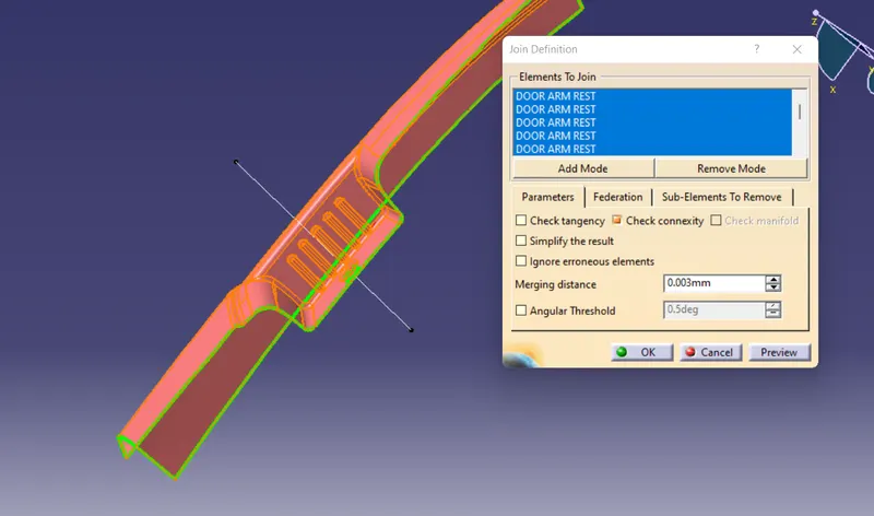
A-surface file given should be checked for uniformity. Join all the patches given to form a single uniform surface with merging distance of 0.003mm.
Tooling axis:
A tooling axis is required to perform draft analysis and creation of B and C surfaces. The surface given could have a side core tooling axis along with the main axis.
Main tooling axis:
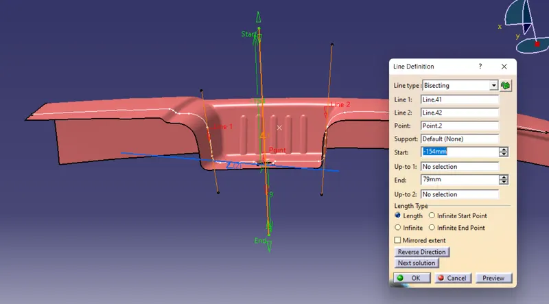
The Main tooling axis is created by bisecting method. Extarct the lower surface of the arm rest and untrim it. Place a point at the centre of the circular hole present. Create an axis system with the point as origin.
The Z-X plane of the axis system is intersected with the A-surface to form a profile. Create two lines from the profile as shown below. A bisecting line is created from the two using bisecting option under line command.
Side core tooling axis:
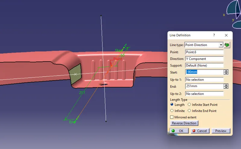
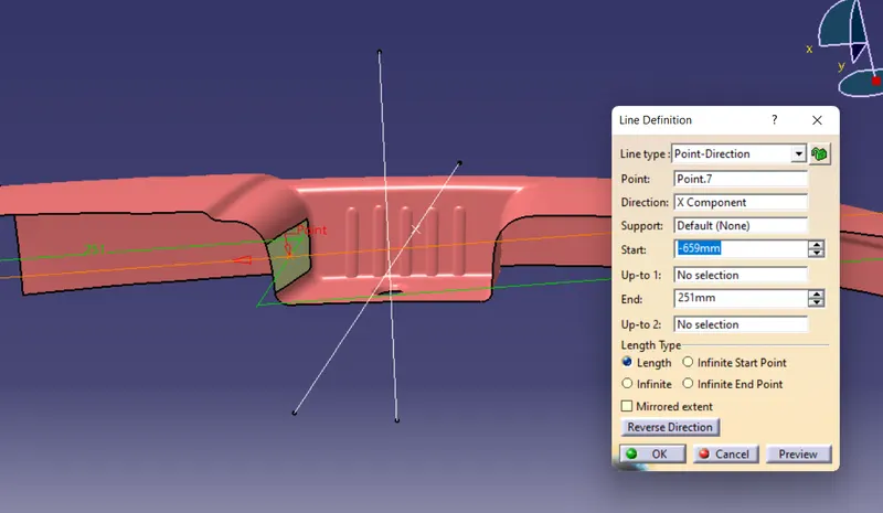
Some components have surfaces at their sides that are difficult to be ejected in main tooling axis direction. Therefore a side core tooling axis is created to facilitate their ejection along other axis. In the given surface the side walls in the bin are diificult to eject under main tooling axis. Therefore, a point is created on the surface as shown. A line through the point in Y-direction is a side core axis ( along Y). Similarly a line passing through a point on one of the side walls in X-direction is another side core axis (along X).
B-surface creation:
The basic process to create a B-surface is to extarct the planar surfaces, offset them, extrapolate to a required extent and trim all into a single entity. Here as per the profile of A-surface, some of the surfaces are created using sweep, multisection commands.
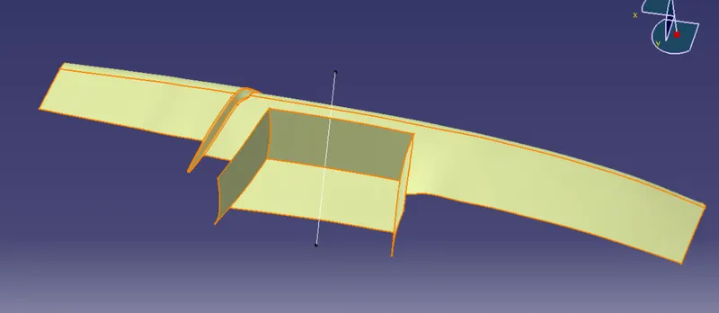
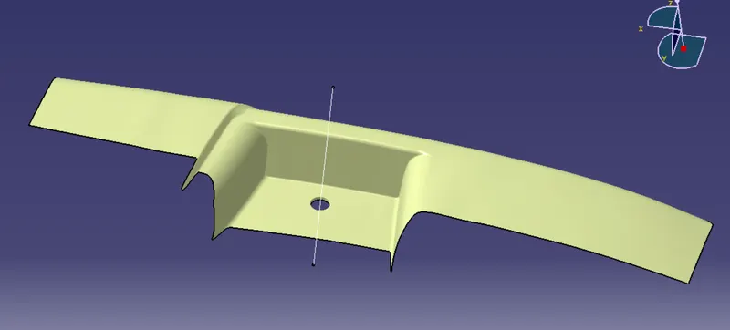
Final B-Surface
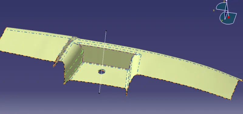
C-Surface creation:
The C-surface is created using sweep command. Some portions of the boundary of A-surface are extracted and swept using "Draft Direction" option in sweep command.
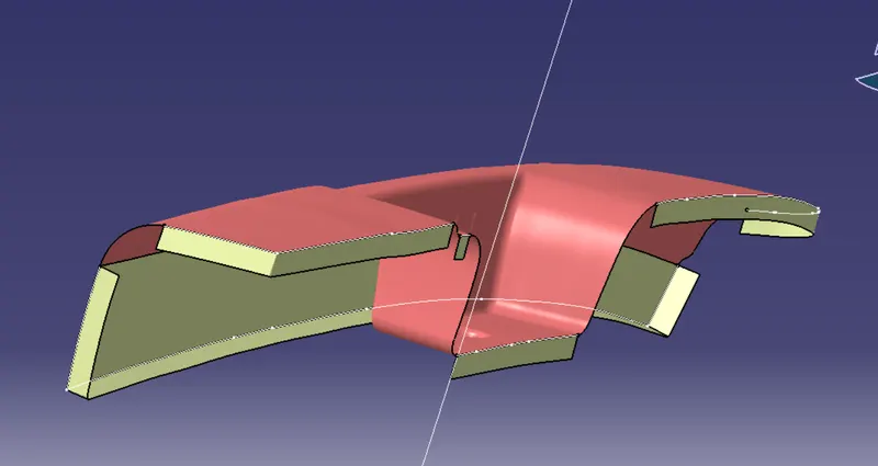
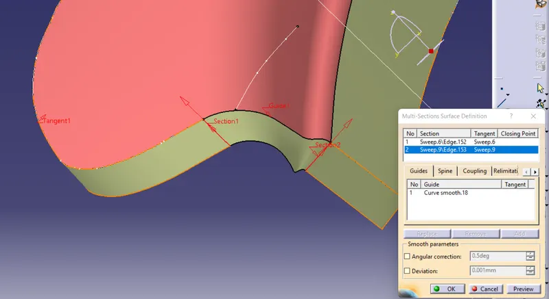
The remanining gaps having fillets are filled with help of multisection surface command.
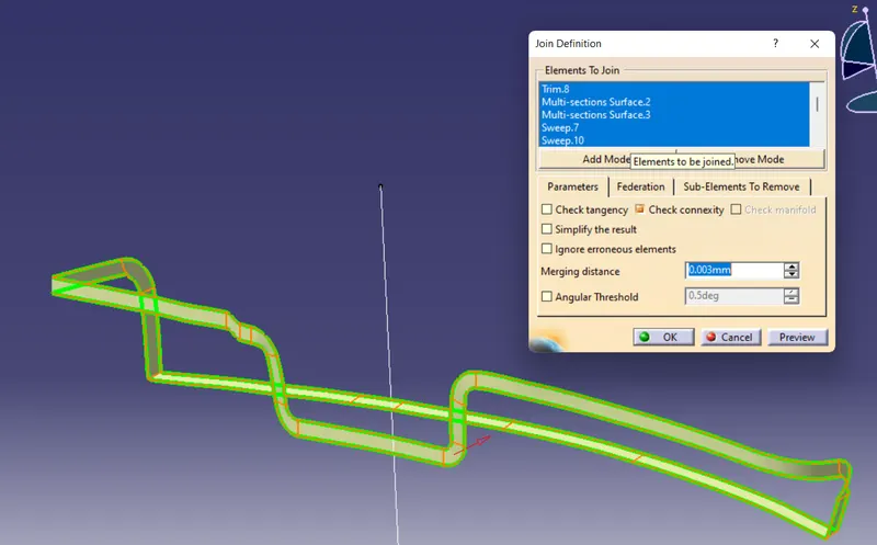
The swept surfaces and multisection surfaces are joined using "Join" command with merging distance of 0.003mm. This is the final C-surface formed.
A,C surfaces are joined and this unit is trimmed with B-surface. The closed surface formed is as shown below.
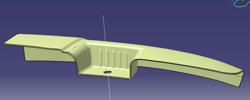
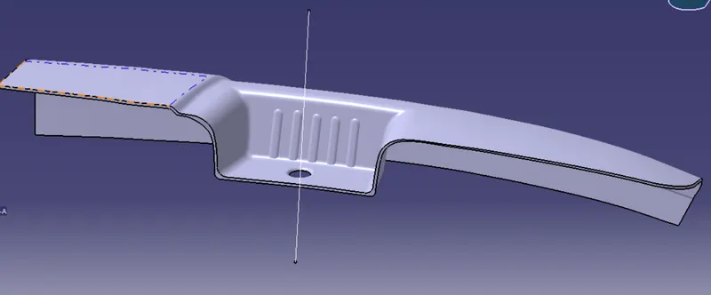
The part body from the surface is formed using "Closed Body" command in part workbench.
Draft analysis:
Plastic components are given some draft to remove them easily from the mold cavity. The draft analysis is performed for Class-A surface and the body of door arm rest.
Class-A surface:
The draft analysis is to done with respect to Main tooling axis and 2 side core tooling axis.
The steps are as follows:
Select the 'Materials' option under View mode customization box.
Select "Feature Draft Analysis" under "Analysis" option.
Orient the compass along the main tooling axis and lock it.
Click on any point on the surface to get the analysis of draft angles on various portions of surface.
Orient the compass along other tooling axes to get the draft with respect to those axes.
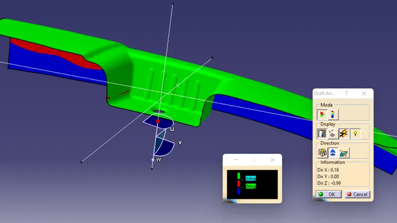
Draft analysis along Main tooling axis
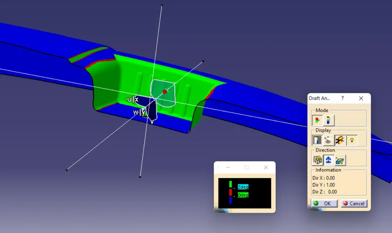
Draft analysis along side core tooling axis (along Y)
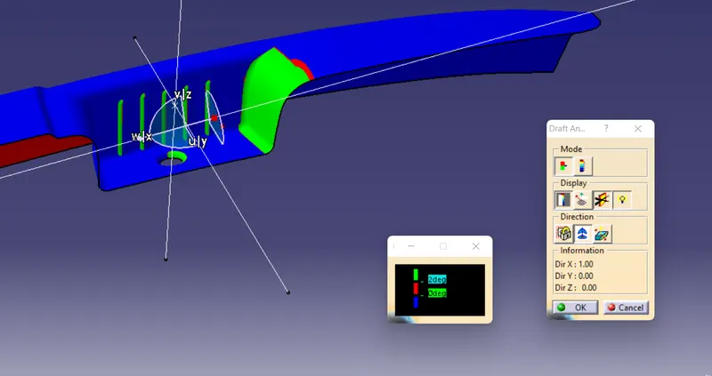
Draft analysis along side core tooling axis (along X)
Draft analysis of solid object:
Similar procedure needs to be followed to perform draft analysis on solid body. Analysis is performed with respect to Main tooling and two Side core axis
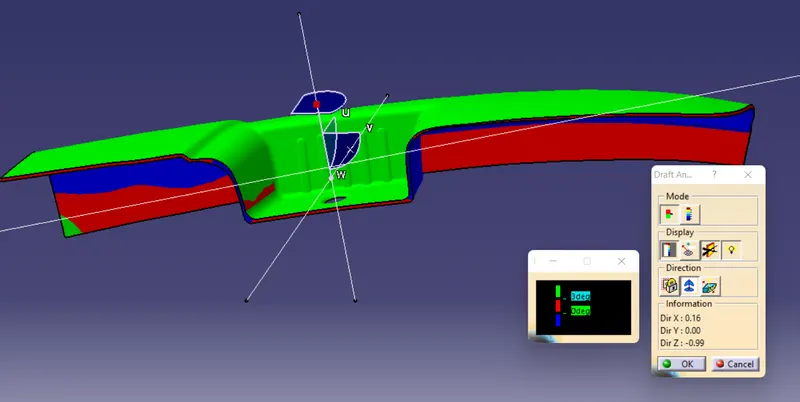
Draft analysis along Main tooling axis
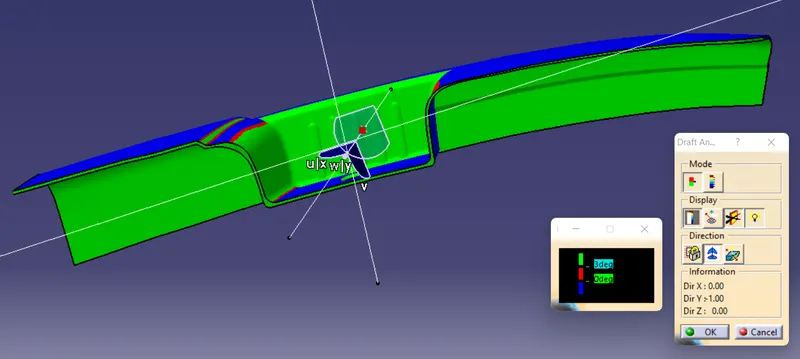
Draft analysis along side core tooling axis in Y-direction
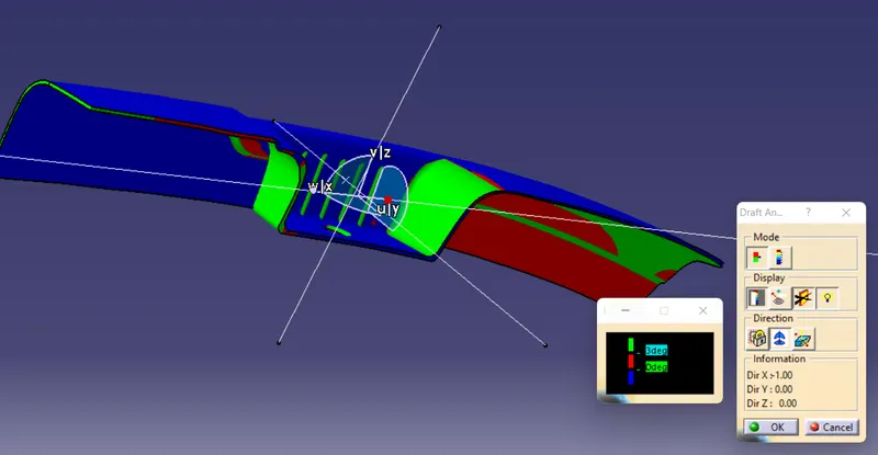
Draft analysis along side core tooling axis in X-direction