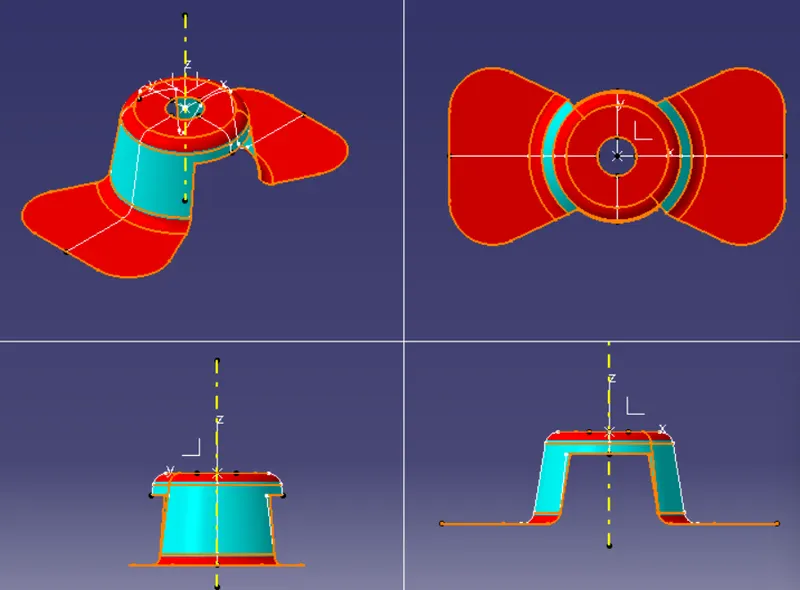
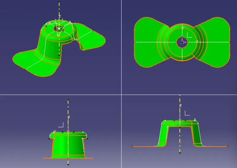
Week 8 - Challenge 1 - Draft Analysis on a Fan Cover
Draft analysis on fan cover
Objective:
To perform draft analysis on a fan cover in CATIA V5.
Introduction:
The components made of plastic or sheet metal while being manufactured would be given some draft on the surfaces. This enables to remove the components easily from the mold or die. Through draft analysis we provide the direction to component in which it can be ejected, and correspondingly measure the draft on the surfaces of the component through this direction. In general, plastic components are given a draft of 3 degree while 0.5 is given to the features inside them. For sheet metal parts, a minimum angle of 7 degrees is given.
Tooling axis:
It is the axis through which the plastic or sheet metal part gets ejected from the mold or die. Here the tooling axis is created with bisecting method.
Procedure:
Before creating tooling axis, ensure the continuity in the given surface. Create a uniform body by joining all surfaces.
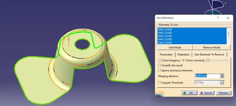
Having a uniform boundary throughout, mark a point at the centre of circle at the top. A seperate axis system is created with this point as centre.
Upon intersection of Z-X plane with surface we get a line formed as shown.
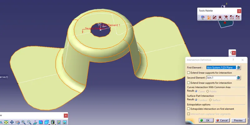
Tooling axis is formed by bisecting two non-parallel lines. The non-parallel lines are formed by 2-point method as shown below.
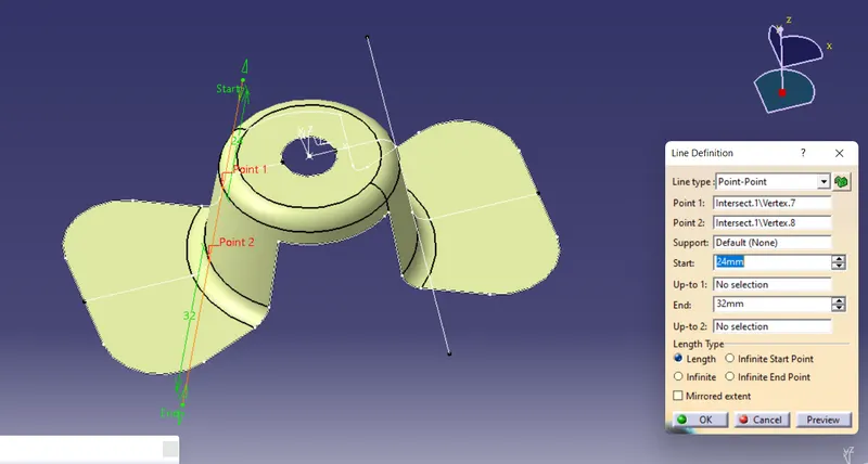
The tooling in X-direction is formed by bisecting option under the line command. The same process is followed by intersecting Z-Y plane and the surface. the axis formed here is the tooling in Y-direction. A final tooling axis is the line formed by bisecting the tooling in X- direction and Y-direction. In this case the tooling axis in both X and Y directions are coincident.
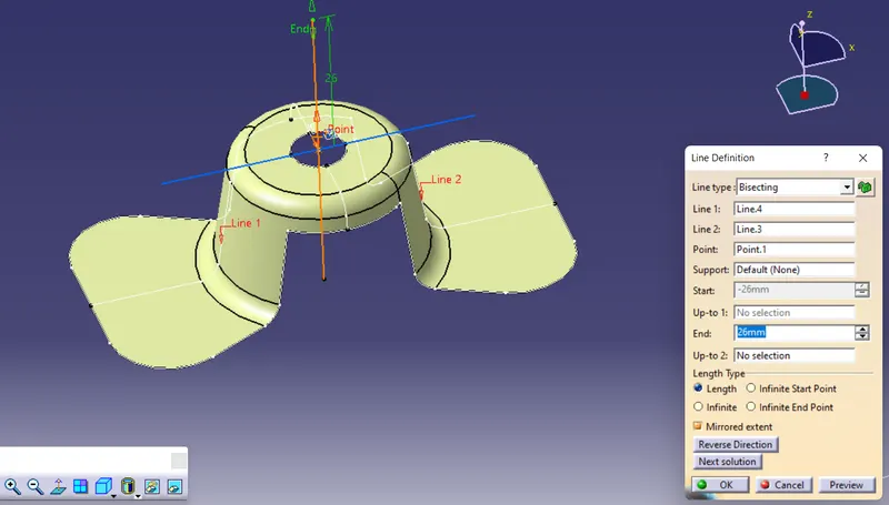
Having the tooling axis, the draft analysis is performed through the following steps:
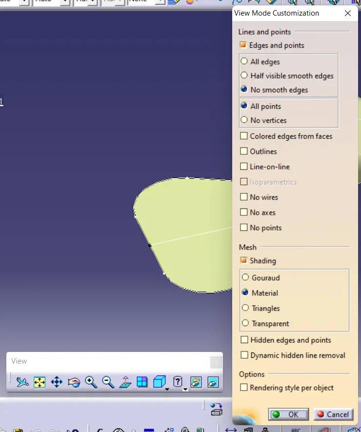
a) Select the material option in the view mode customization command in the view toolbar.
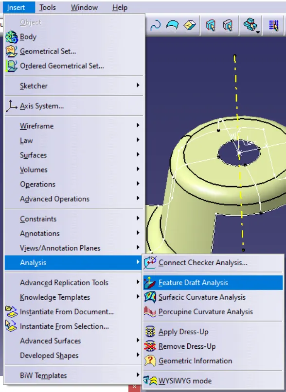
b) Select the "feature draft analysis" command under the analysis option in the insert toolbar.
c) A draft analysis box is displayed. Under direction, select the compass option. Then orient the axis of compass in the tooling axis direction by dragging it towards the axis.
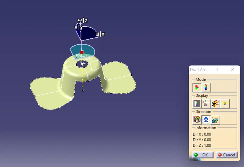
d) Lock the direction of compass by using the lock symbol under direction option.
e) A point then appears upon moving mouse anywhere on the surface. Click on the surface and select the first command underdisplay option. The given component is then highlighted with various colours showing the value of angle in a mini window.
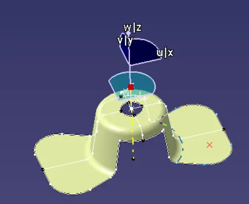
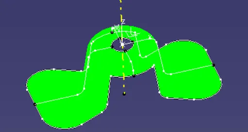
'The analysis under the running point' command helps to check the draft angle on the surface wherever the mouse is pointed. The colour scaling could be adjusted as per our needs. The direction of draft can be reversed to ensure the correct one.
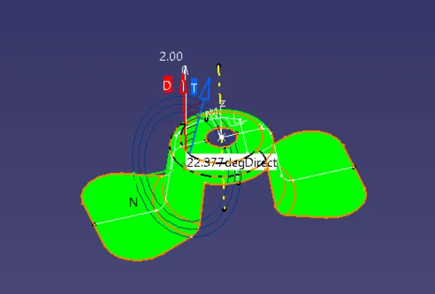
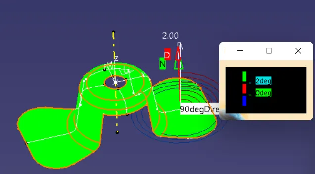
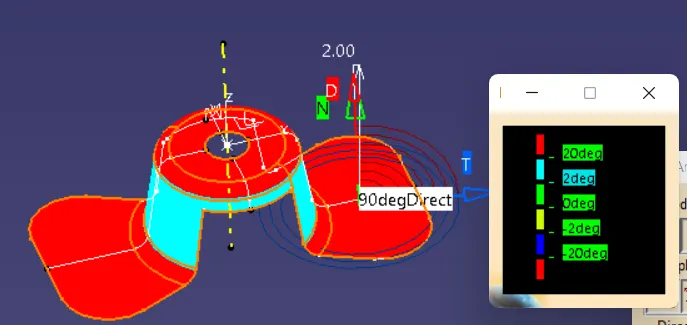
Click on 'Ok' button to save the analysis.
Draft in various orientations: