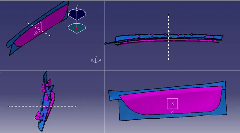
Week 9 - Project 1 - Door Applique Design with Engineering Features
Door Applique design with engineering features
Objectives:
a) Create B and C surface from A-surface of a door applique. Create surface for door applique attachment.
b) Create heat stakes, 2-way and 4-way locators on door applique body.
c) Perform draft analysis in Door applique and door attachment surface.
Door Applique:
A component in door assembly responsible for creating good aesthetic look.
Tooling axis creation:
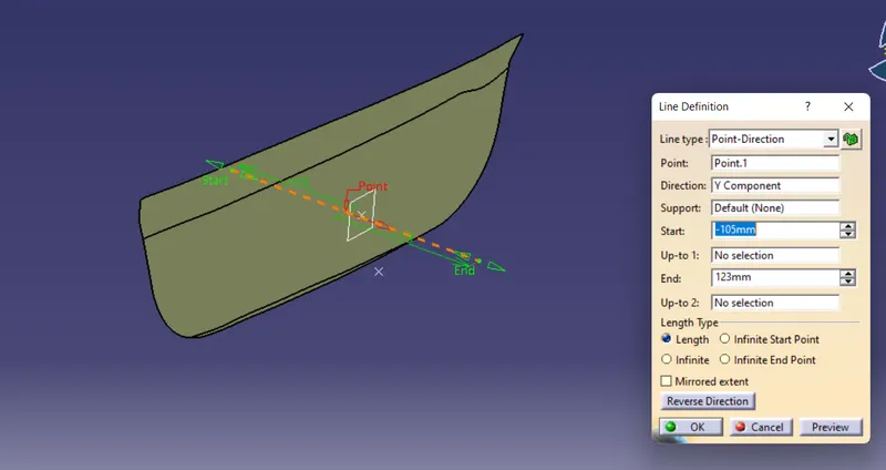
Before creating tooling axis check the continuity of A-surface. Ensure a uniform outer boundary on it. Extract the bottom portion on the class-A surface. Position a point at the centre of extracted surface. In this case the tooling axis is a line perpendicular to the extracted surface. Create a line passing through the point in Y-direction. This is our tooling axis.
Class-B creation:
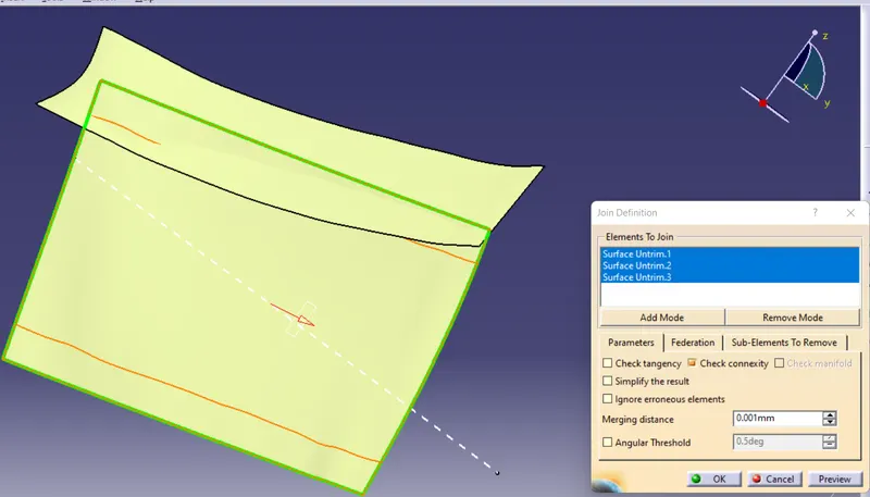
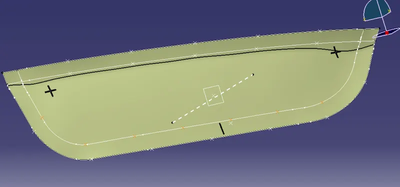
Extract the planar surfaces of class-A which have no fillets. Untrim each of them. Join the two untrim surfaces as shown below.
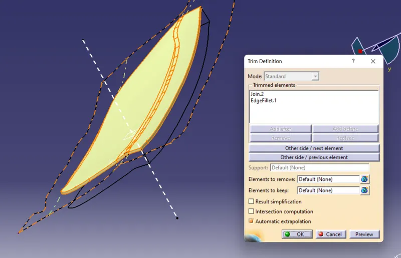
Offset the Joined surface and the remaining one surface to a distance of 2.5mm. Extrapolate them sufficiently and trim them into a single unit. Fillet the sharp edge considering 13.5mm as radius value.
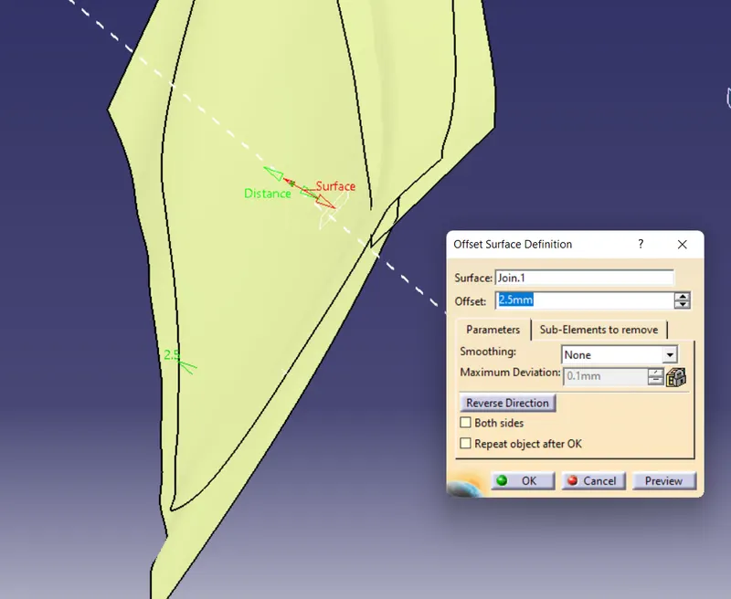
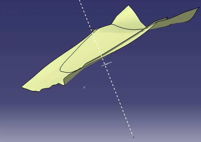
This is the final B-Surface required.
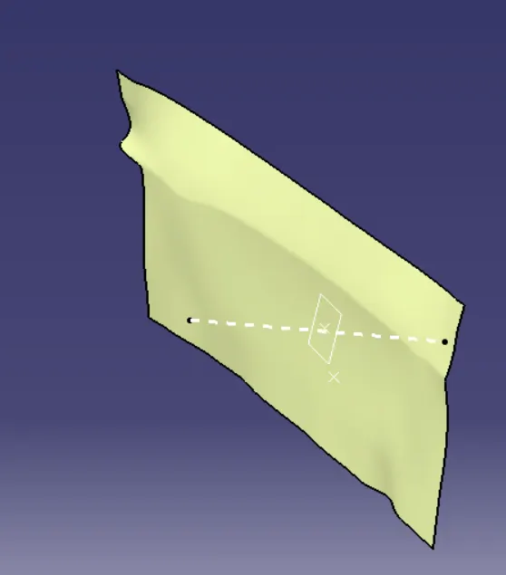
C-Surface:
Extract the outer boundary of A-surface in two halves. Smothen the extracted curves by giving maximum deviation of 0.003mm. Using these curves create surfaces using draft option in sweep command. The two surfaces obtained are then extrapolated and trimmed to form a continuous C-surface.
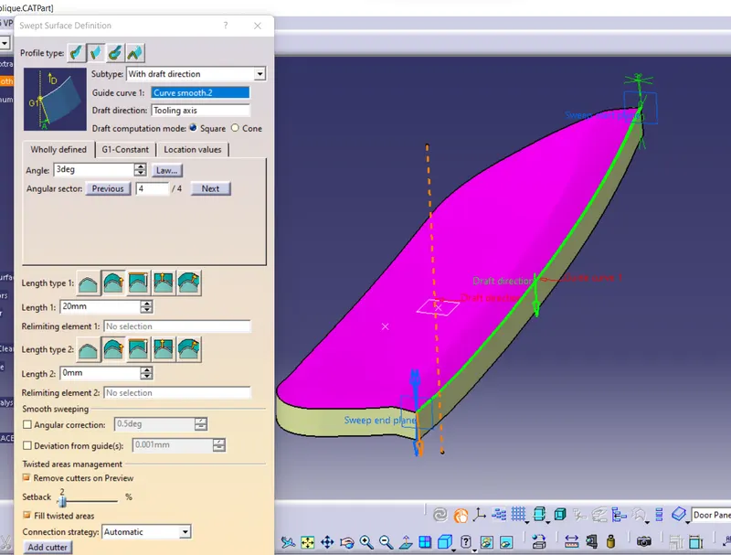
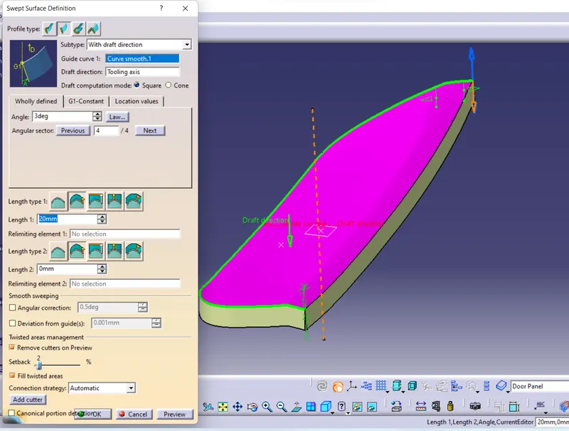
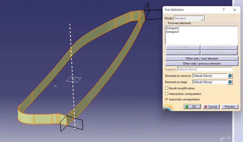
The final closed surface is obtained by Joining A,C surfaces and trimming it with B-surface. The closed body of door applique is formed by using closed surface command in part workbench.
Door attachment surface:
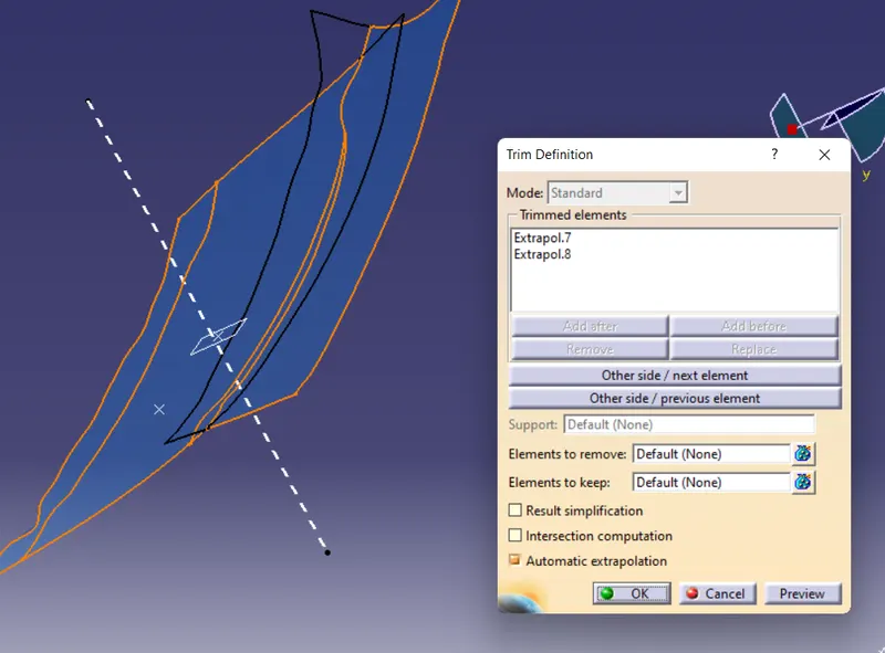
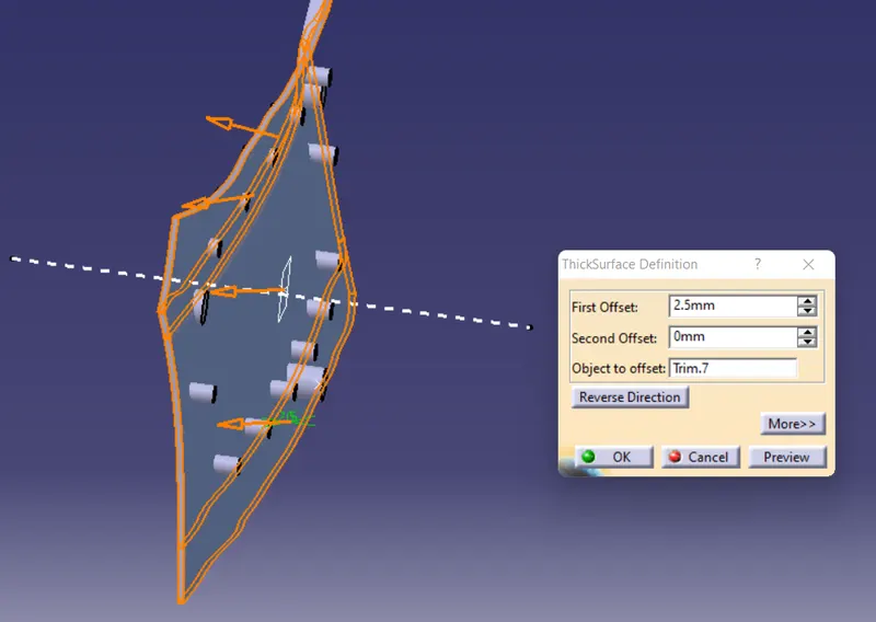
The process of creating door attachment is similar to creating the B- surface. Extract all the planar surfaces of class-A and untrim them. Join two surfaces that are in same plane. Offset the joined surface and upper surface to a distance of 15mm. These surfaces are then extarpolated more and trimmed into single unit.
The solid body of the door attachment is formed using thicken surface command, giving 2.5mm as thickness.
3-2-1 Principle of location:
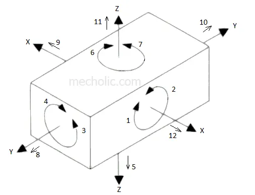
Any object in general has 12 degrees of freedom or movement.
Translation:
Translation along +X and -X direction
Translation along +Y and -Y direction
Translation along +Z and -Z direction
Rotation:
Clockwise and counterclockwise about X-axis
Clockwise and counterclockwise about Y-axis
Clockwise and counterclockwise about Z-axis
To restrict a body at a particular position, a minimum of 11 degrees of freedom should be restricted.
2-Way and 4-Way Locators:
4-way locator restricts translatory motion along 2-axes. 2- way locators makes fixing easier. The rules of Rib design are followed in deciding thickness, height of locators. A draft of 45 degree is given to all surfaces standing on the door applique.
Ensure that distance between top of locator and the lower surface of door applique should be same for all.
Extract surface of door applique and create a point on centre of the extract. A plane is formed with ZX plane and point as reference. This is suitable for creating sketches.
4-Way locator:
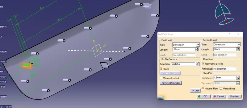
A sketch containing 2 bisecting perpendicular lines having 15mm each. The sketch is made into a body by Pad command following the rules of rib design.
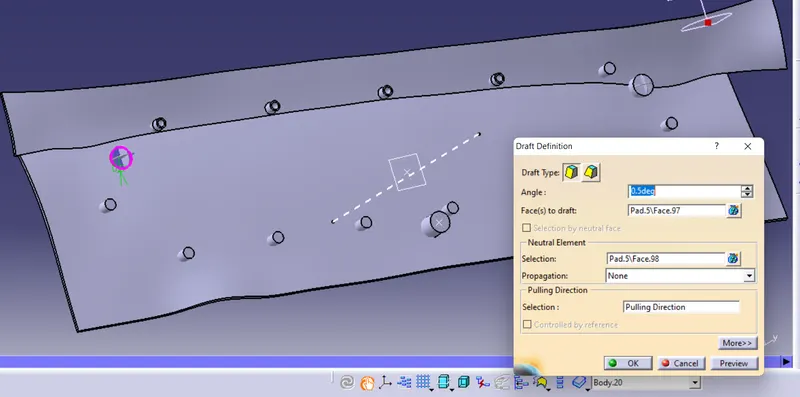
The locator is given 0.5 degree draft. Top edges are 3mm 45degrees chamfered. Surfaces are filleted with 0.3mm radius while edges are given a fillet of 3mm radius.
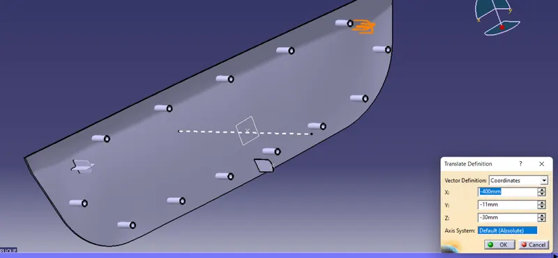
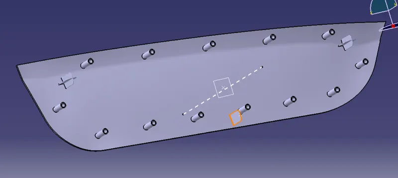
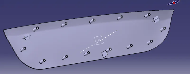
The same locator is generated by copy pasting it. It is then translated to other of door applique as shown.
2-Way locator:
A sketch of 15mm vertical line is created. The solid body is generated using Pad command. Thickness is given following rib design rules. Draft , chamfer, fillet are provided similar to 4-way locator. The 2-way locator is kept at lower edge of applique between 4-way locators.
Heat stakes:
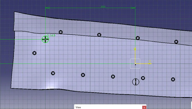
The upper and lower edges of Class-B are extracted seperately. Using point planes and repitition option in point command, multiple points are created using appropriate number of instances. Make sure that the points would not interfere locators. The points are formed in a seperate geometrical set in tree structure.
The lower surface of door applique is extracted in two halves. Using parallel curve option the two edges extracted earlier are offset to a distance of 15mm. Multiple points along both the offsets are then created using point planes and repitition command.
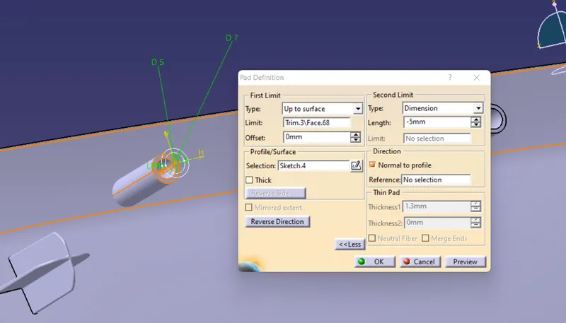
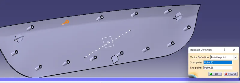
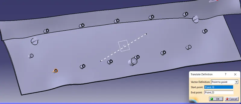
Now using first point as projection a sketch of 2 concentric circles is created. This is converted to solid body using pad command. By copying and pasting it each heat stakes is translated to all points using point to point in translate command. Now that all heat stakes, locators are formed, each of them is trimmed properly on door applique.

Counter clearences on door panel:
An appropriate clearence should be given for locators, heat stakes with door panel. For this solid objects (circles that are pad) are created at each place where locators, heat stakes are present. These are trimmed from the door panel to get the required clearences.
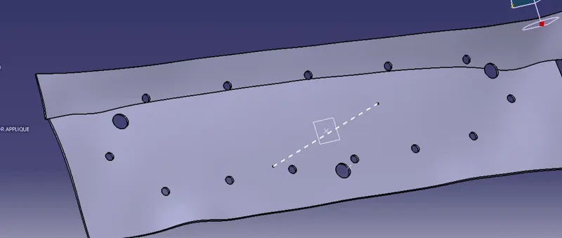
Ensure that locators have 0.1mm clearence and heat stakes have 0.5mm clearence.
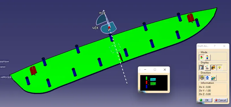
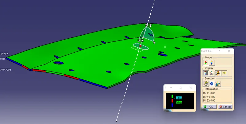
Draft analysis:
Draft analysis is performed through following steps:
a) Select material option under "View mode Customization"
b) Select "Feature draft analysis" under Analysis option.
c) Click the compass button in draft analysis box and orient the compass in tooling axis direction
d) After proper prientation lock the compass oreintation and click anywhere on the surface to get the coloured view of draft on surface.
Draft analysis on Door applique:
Draft analysis on Door panel:
Design in various views: