Week 8 - Challenge 3 - Coin Holder Design
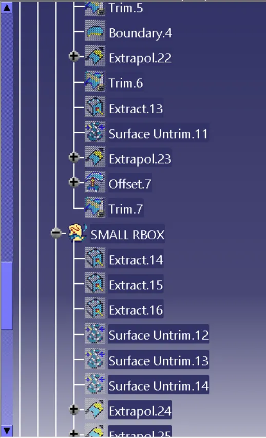
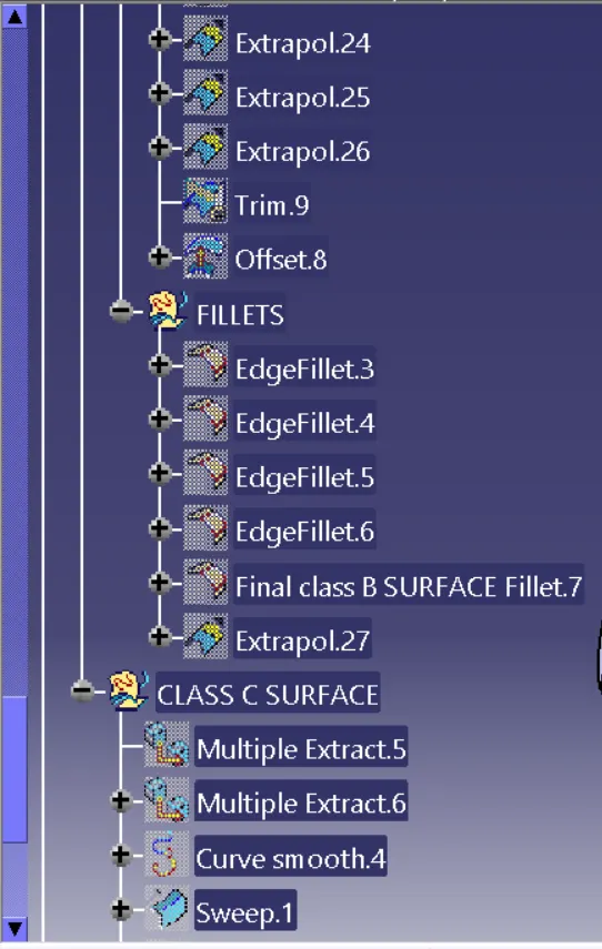
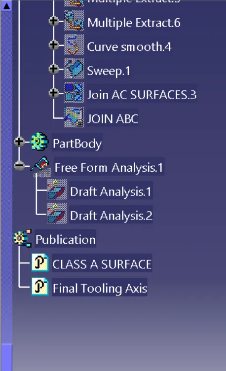
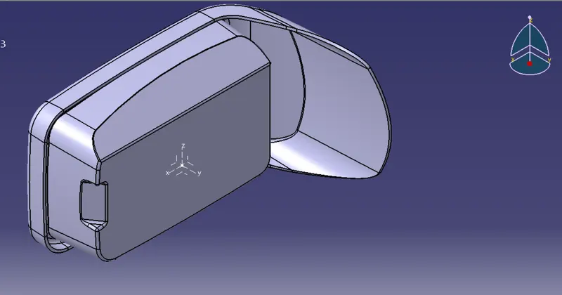
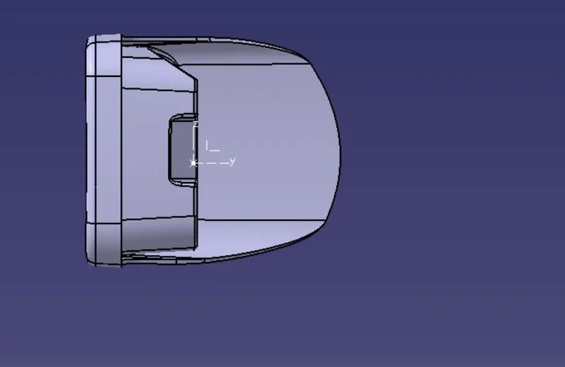
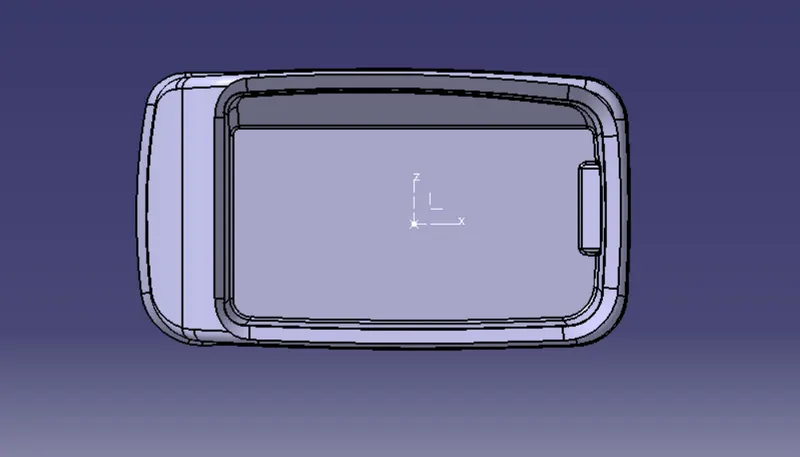
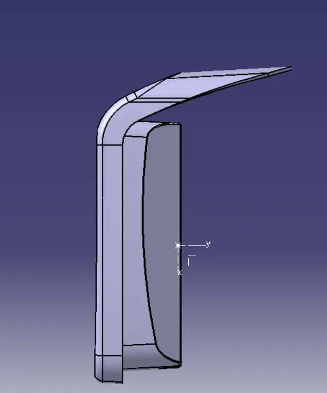
- DRAFT ANALYSIS FOR CLASS A SURFACE :-
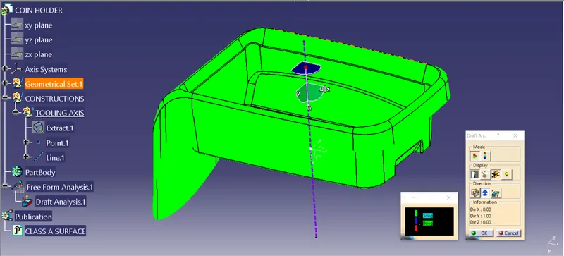
- DRAFT ANALYSIS FOR SOLID BODY :-
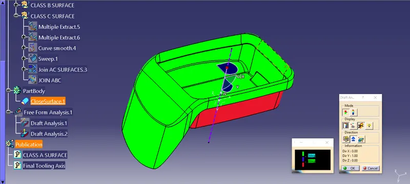 REPORT FOR THE COIN HOLDER FEASABILITY CHECK FOR GIVEN CLASS A SURFACE :-
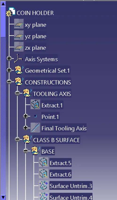
 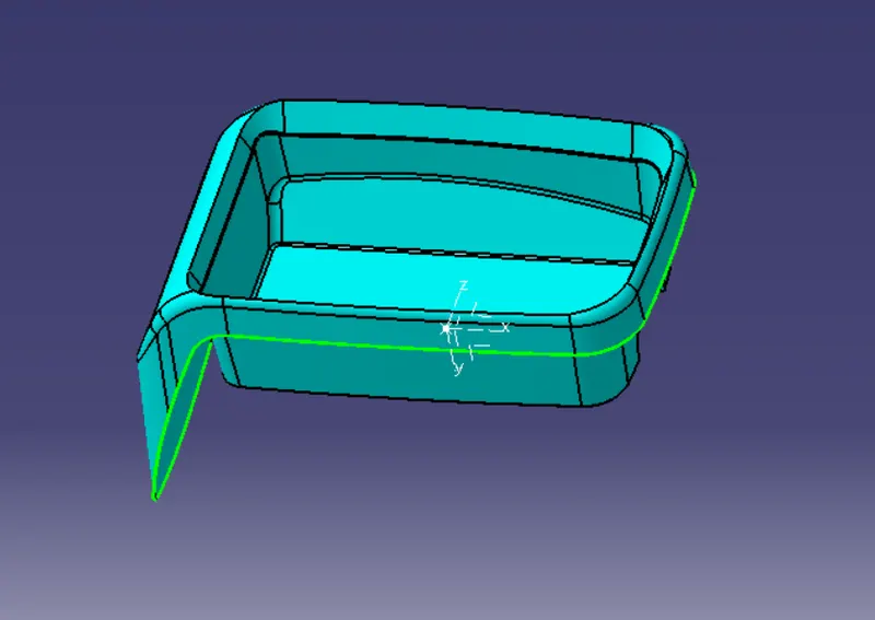 Here in the given Class A Surface model we have to check that any unjoined surfaces are present we have to join together and proceed for creating tooling axis. TOOLING AXIS FOR CLASS A SURFACE :- For creating a tooling axis first we need to check for the direction by which the model is possible for manufacturing(by following core and cavity direction). Then we have to proceed for tooling axis creation ie;by which process the given class A surface maintains 3 deg draft (either by taking the any of the standard surface from the model or taking normal to surface or by bisecting method ). We should always enable the material mode for draft analysis. Go to insert ->Analysis ->Feature draft analysis . Place the compass on the tooling axis ,then select the compass option in the dialog box and then give the 3 deg . CREATION OF CLASS B SURFACE :-
 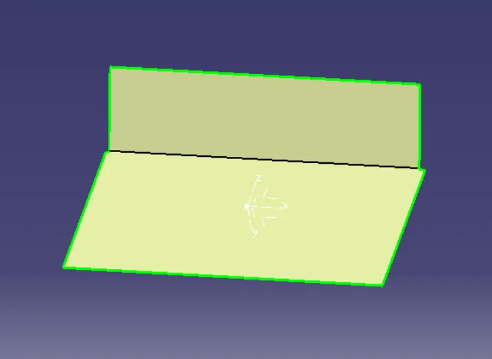 In this select the base ->extract->untrim->offset . (offset means for the given thickness value)
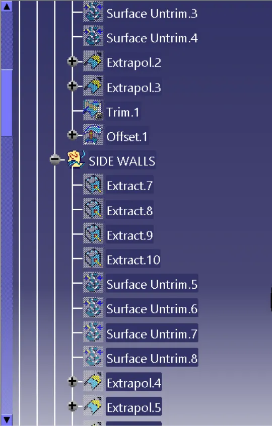
 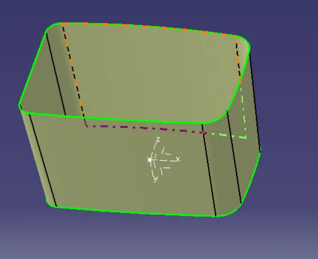 after the base, select the side walls ->extract->untrim->offset. and create the fillets required.
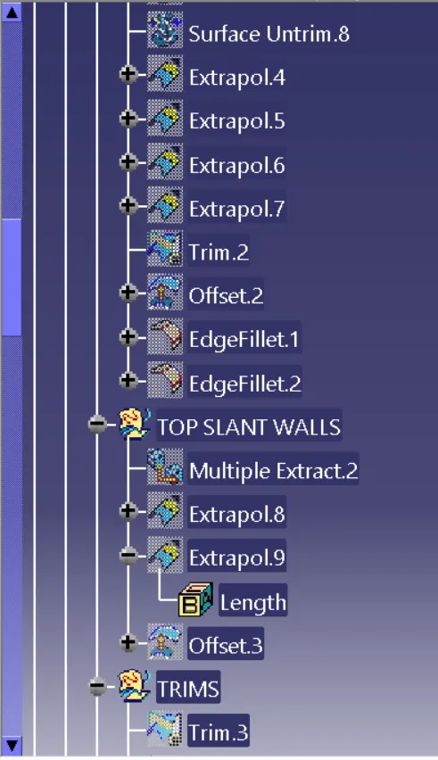
 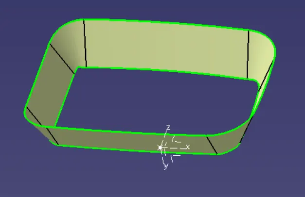 Select the top side walls->extract->untrim->offset.
 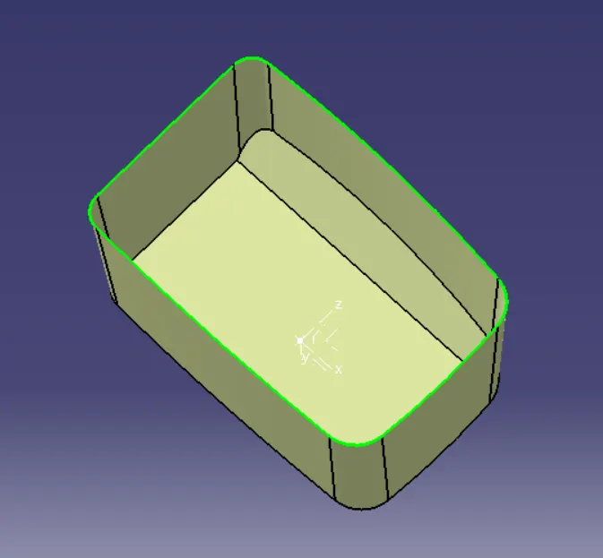 go to trim ->select the base and side walls->now the base and side walls are joined together.
 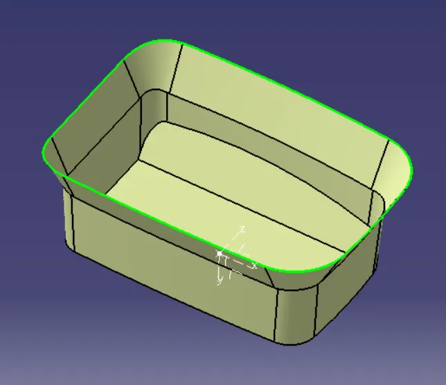 go to trim ->select the top walls and trim 1 .Now the trim1 and top walls are joined.
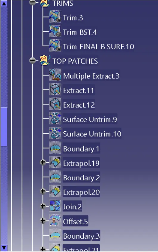
 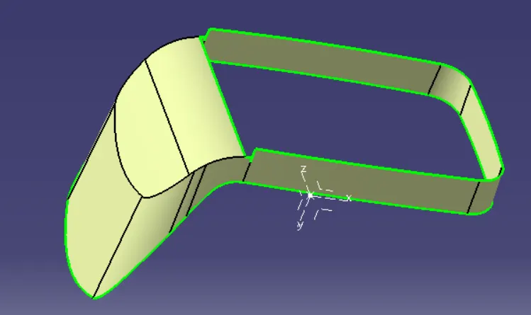 now create the pateches go to multiple extract->select the pacthes of remaing ->extrapolate->trim.
 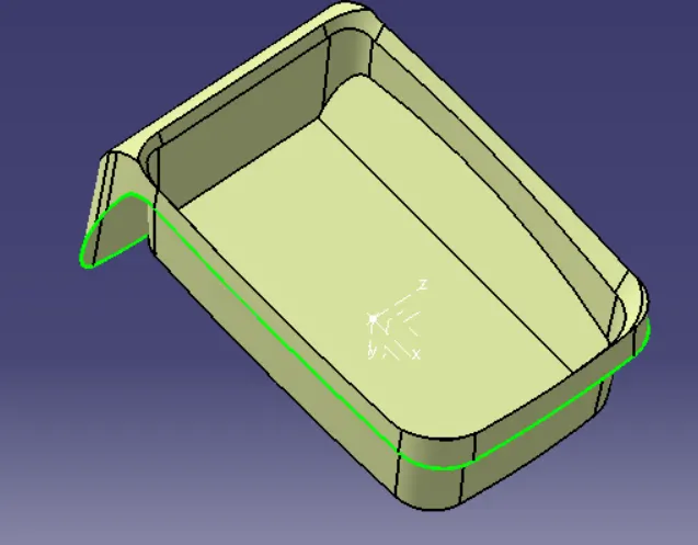 now go to trim->select trim 2 and patchches .
 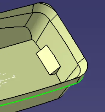 select the walls of rectangular small box present in the model go to extract ->untrim->extrapolate->trim .box is created, now go to trim ->select trim 3 and rectangular portion.
 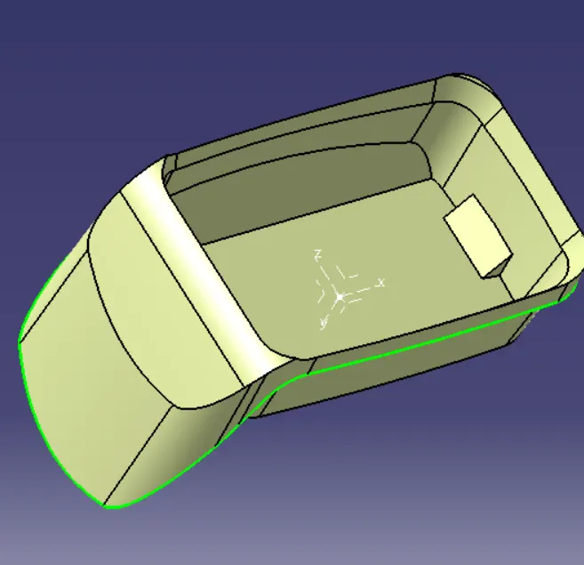 now the required class B surface is created and required fillets are provide for the model . CREATION OF CLASS C SURFACE :-
 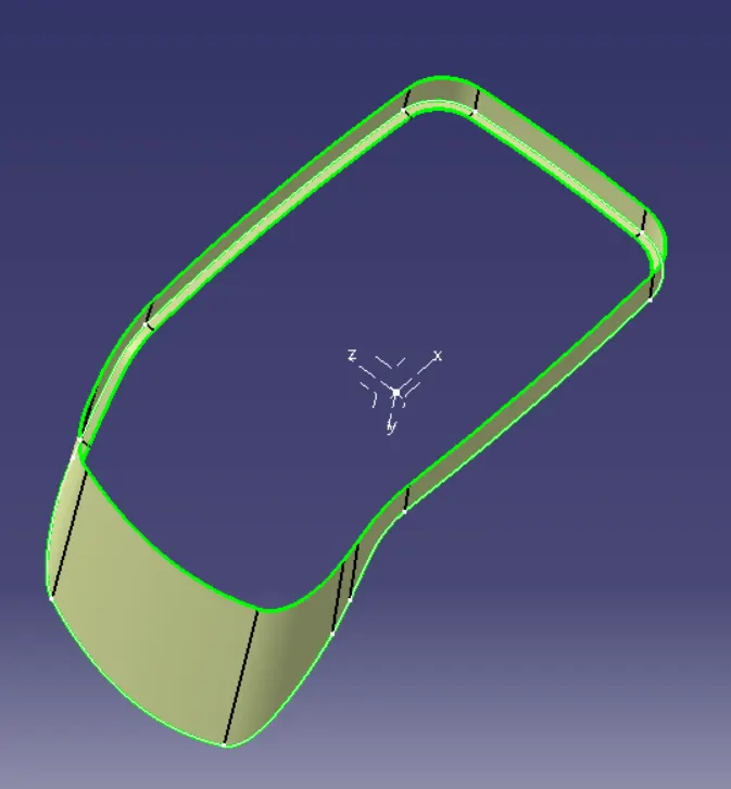 now the class c is created by the reference of class A surface . extract the patches(reference surfaces ) and extract the boundary . go to sweep->select line type->select with reference surface->now select the patches as reference surface and guide curve as boundary->the class c is created perpendicular to class A.
 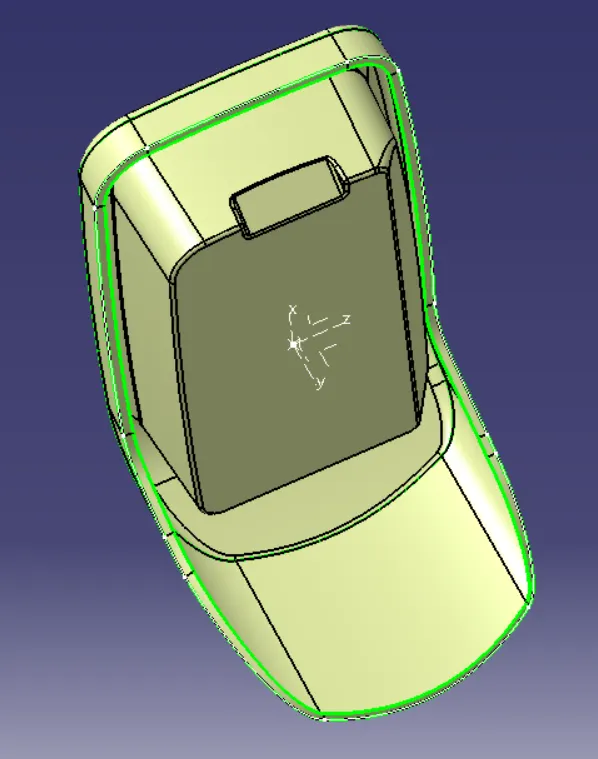 Now join Class A and Class c Surfaces together. JOIN CLASS A,B&C :-
 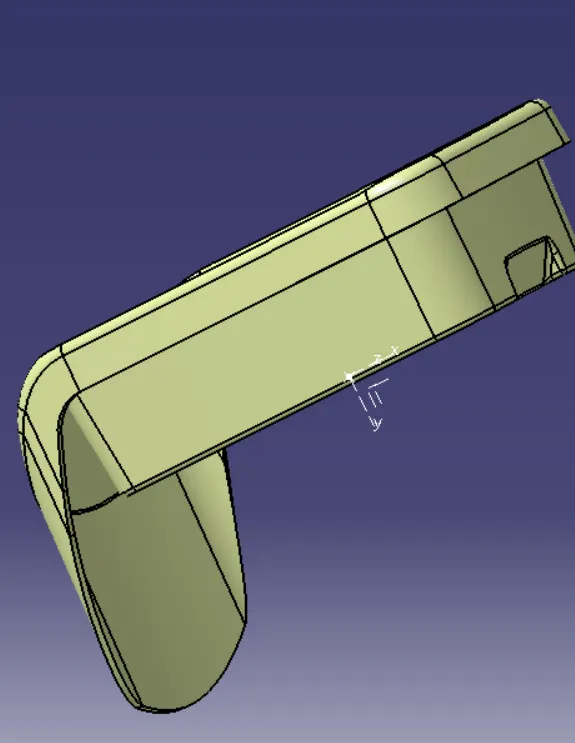 Go to trim -> select class Ac and class b ->now the class ABC surfaces are joined together. SOLID BODY :- Go to part design wb ->select closed srface ->select the Class ABC surafce DRAFT ANALYSIS FOR SOLID BODY:- GO to insert->analysis->feature draft analysis ->drag the compass and place on the tooling axis ->click on the compass option and select on the solid body now the solid body shows the colours of draft angles for A B C surfaces.