Week 8 - Challenge 3 - Coin Holder Design
Aim : To publish claas A ,B & C surface with tooling axis & show draft analysis
Objective :
Create the Coin Holder Plastic component through the given Class-A surface. To begin with, the tooling axis for the given Class-A Surface should be created meeting the requirements of the draft angle and at the end perform the Draft analysis on the model.
Note :
Take the Thickness of the component to be 2.5 mm
Procedure of Class A, Class B & Class C surface and tooling axis with draft analysis
Class A surface
here is we provide the coin holder catia file with this achallenge we use this file and create the B surface and C surface
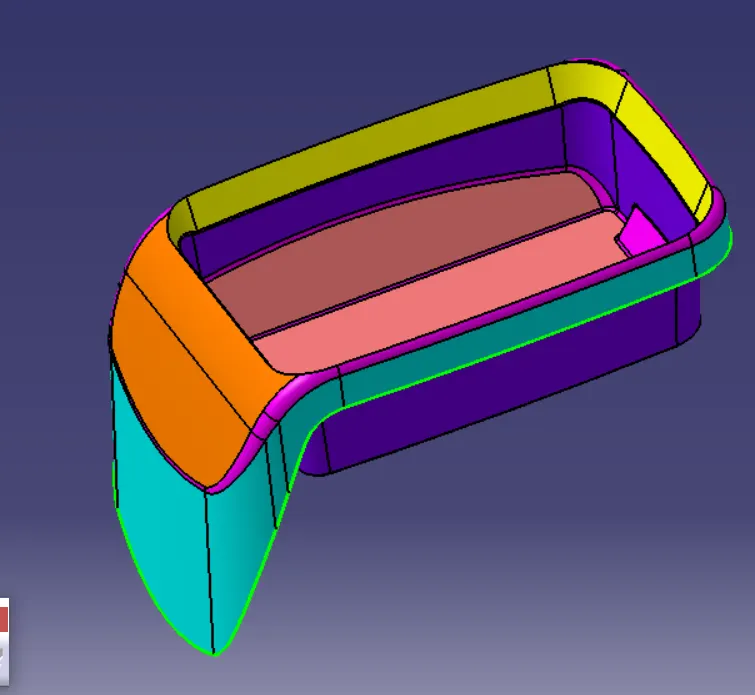
Tooling axis :
here is we used the class a surface which is given in the challenges than extract the base surface than create the point by surface reference and using that point we create line than that line create the tooling axis and used this axis for draft analysis
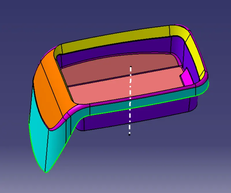
B Surface :
here is B surface Surface needs to be created according to the class-A surface so 1st we create side walls so extract all 4 surfaces of the sidewall of the coin holder. Then these surfaces are first untrimmed to get the intersection for surfaces so that a replica can be created. If the surfaces are not intersected, then extrapolate by point continuity propagation is used to make these surfaces have an intersection between them Lastly, the surface trim is used to get the replica for the inclined surface. Now, the thickness of the final component is 2.5mm so this obtained surface is offset below by 2.5mm. Like that the rest of the region is extracted and trimmed to get the final B surface
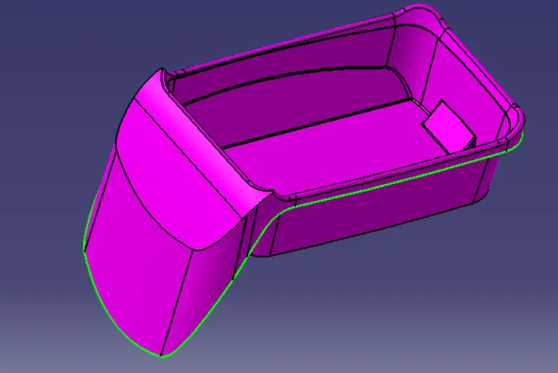
C surfaces :
here is we 1st multipaleextract 1st extract the border than extract the side walls or flanges than we used sweep opertion to create the c surface so in that we select draft in that surface with refrence than select angle 90 and direction inside and create c surface
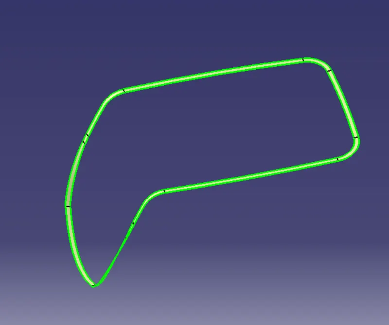
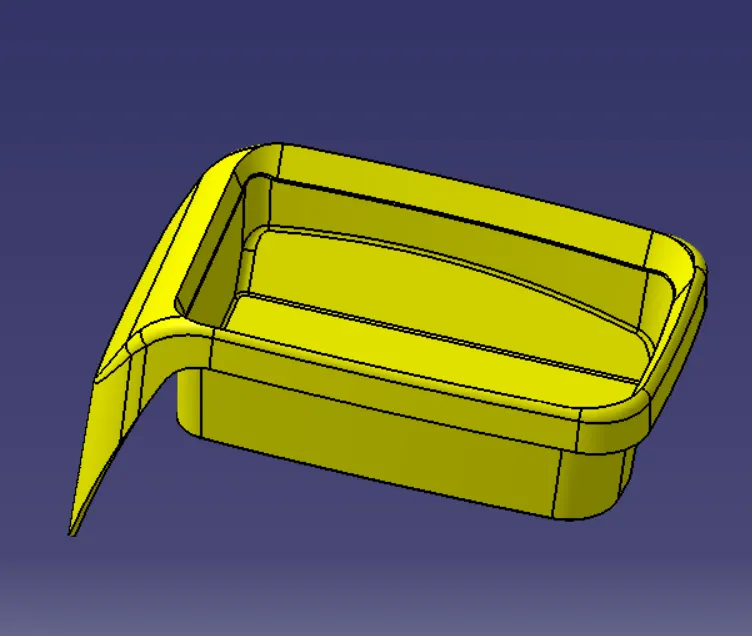
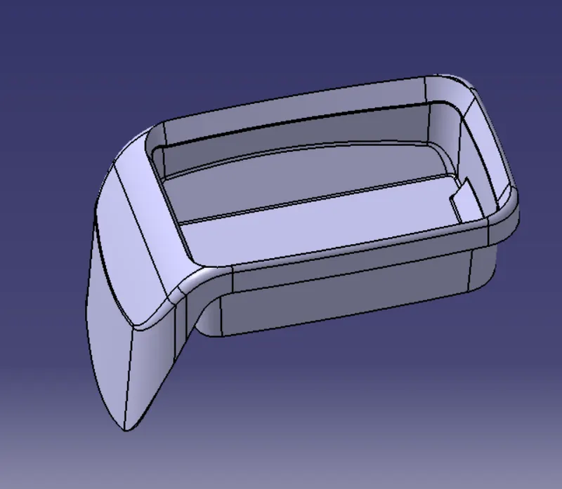
than join it c surface with a surface than trim it with b surfaces get final out come than we create plastic model by using close surface
Closed surface
Draft analysis :
To perform the draft analysis the view parameters are first set to material mode.
Then go to Insert and goto the analysis in that feature draft analysis.
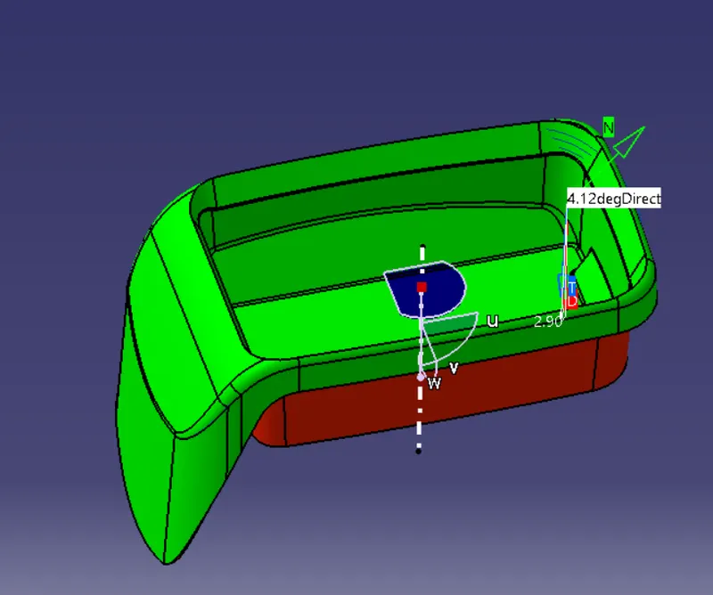
First, select the axis system and drag the axis system to align and coincide with the tooling axis and lock the orientation. This axis system defines the draft direction according to the tooling axis.
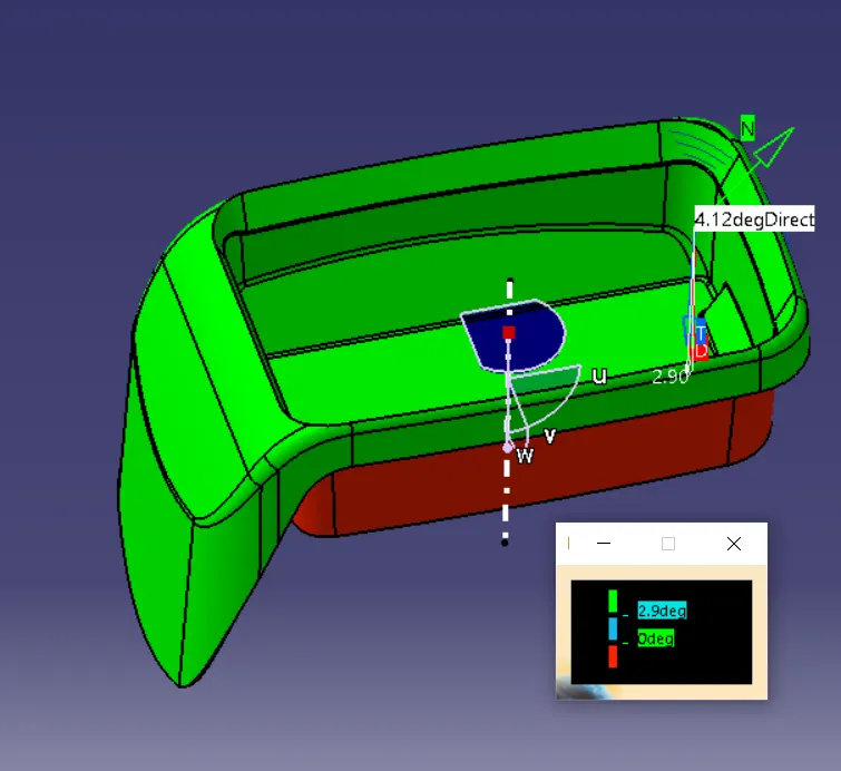
Switch on the color scale and set the minimum draft value. Here it is set to 3 degrees and it will be displayed in green color. Any draft angle below 0 degrees will be shown in red color.
Now select the running point tool to measure the draft angle at the various locations and then if all surface passes the draft analysis switch on the light effect that will show the component in green color if the component has the required draft angle.
The final draft analysis shows the green color surface having the draft angle above 3 degrees and red or cyan color shows the draft angle below 0 degrees.
All the surfaces with green can be easily manufactured with the injection molding but the read color surface which is a negative draft cannot be ejected or manufactured with the main tooling axis.
The solution for this is to have another tooling axis that captures all the rest surfaces but this is not feasible or the last option to make changes in the A-class surface.
Note : in this challeges we attch the catia part file pls refer it