Week 8 - Challenge 3 - Coin Holder Design
Challenge 3 - Coin Holder Design
AIM :
- To Create the Coin Holder Plastic component through the given Class-A surface by maintaining the thickness of the component to be 2.5 mm.
- To begin with, the tooling axis for the given Class-A Surface should be created meeting the requirements of the draft angle and at the end perform the Draft analysis on the model.
OBJECTIVES :
- Checking continuity of class A surface.
- Deciding feasible tooling direction & creating a tooling axis.
- Performing draft analysis on class A surface.
- Creating class B surface from given class A surface.
- Creating class C surface to join A & B class surface.
- Creating solid features by using the closed surface.
- Performing draft analysis on the final plastic component.
MAIN REPORT:
Types of Surfaces and their importance for an Automotive Plastic Designer:
- Class A Surface: Class A is an aesthetic surface with the highest quality finish. Most Class A Surfaces for an Automotive Component are made using 'Autodesk-Alias' based on the final Concept-Sketch. All Class A surfaces should have 'Curvature-Continuity' which means the continuity between the surfaces should share the same boundary. It is taken as a reference by the Automotive Plastic Designer to create 'Class B' and 'Class C' Surfaces.
- Class B Surface: The Class B Surface resides below the Class A Surface at a certain thickness. It is created using Engineering Principles that consist of all the necessary features such as Ribs, Bosses, Snaps, etc. This surface isn't visible to the observer from the outside.
- Class C Surface: The Class C Surface is 'Class A' and 'Class B' joined with each other.
Now, we will begin by checking the State of Connectivity for the Class A Surface and ensure that there are no gaps between the surfaces as all the surfaces should be joined well together with each other and shouldn't consist of any discontinuities between them.
Our Class A Surface:
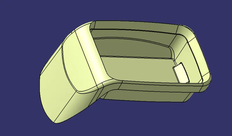
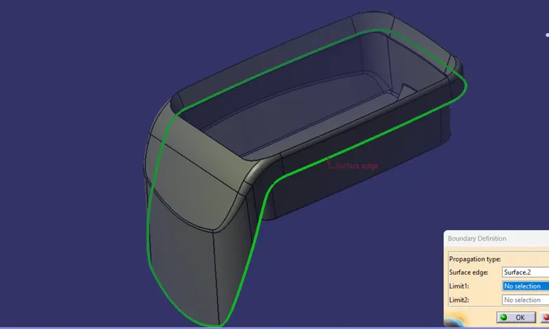
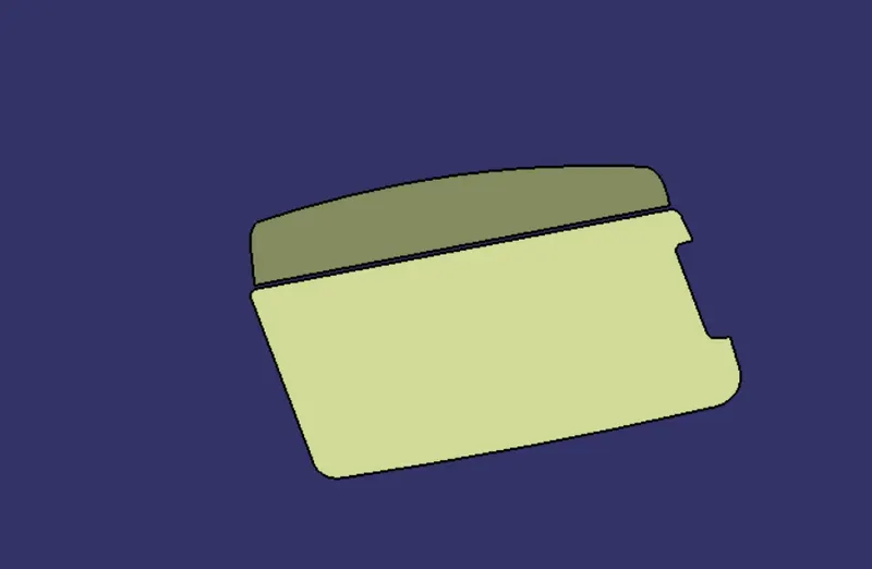
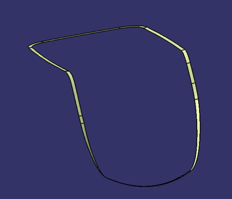
Firstly, we have to check the continuity of the given class A surface to ensure the class A surface is properly joined and that no discontinuity is present. This can be done by using the join or boundary command in CATIA. By looking visually below the image we see that surface has continuously connected boundaries as highlighted by a green line. Also, this boundary is separated into two domains.
Creating main tooling axis :
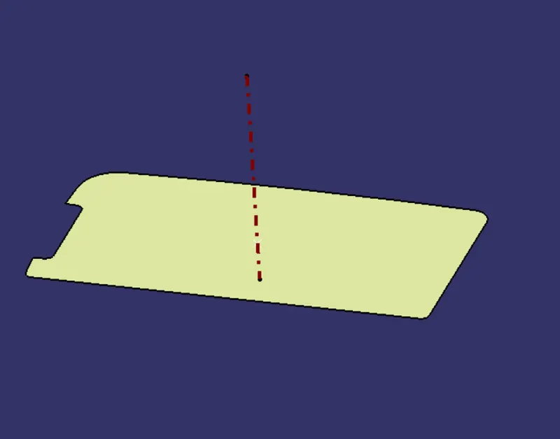
- First, extract the base surface & create a point on that surface. Insert the axis system at that point. Take the intersection of the class A surface with the XZ plane of the axis system. Create two lines along the vertical faces. Create a line using bisecting method & passing through that point.
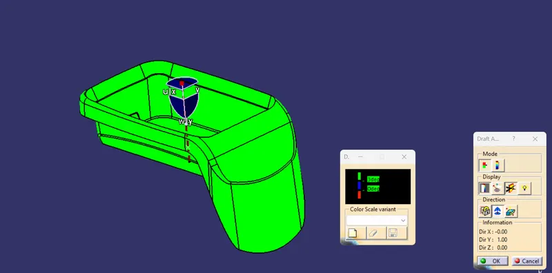
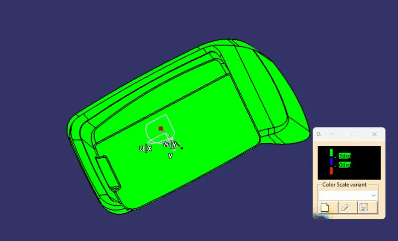
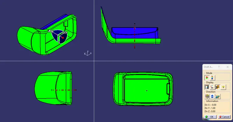
- Perform draft analysis using that line as a tooling axis. We observe that a few faces of components are not in green. So tilt the compass wise to achieve the entire top surface & back surface are in green color except for the pocket surface. Lock the position of the compass.
- Create the line in by choosing direction as compass direction & passing through the point on the base surface. This is our main tooling axis. After that unlock the compass & reset it.
Draft Analysis on Class A Surface:
Creating class B surface from given class A surface.
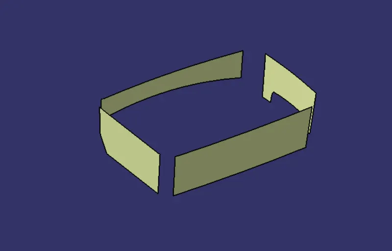
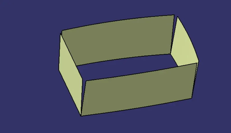
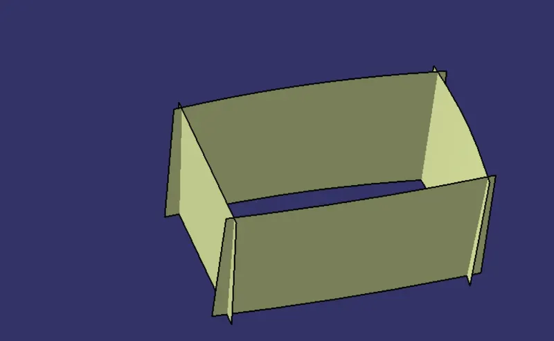
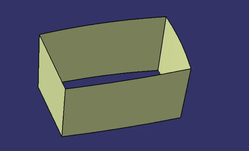
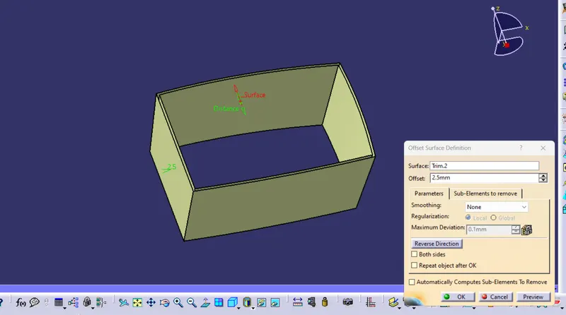
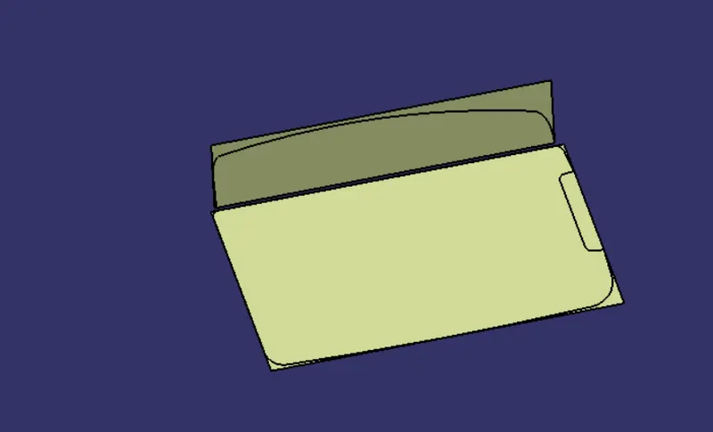
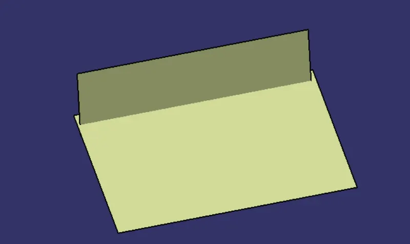
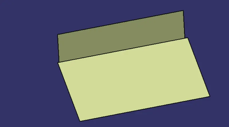
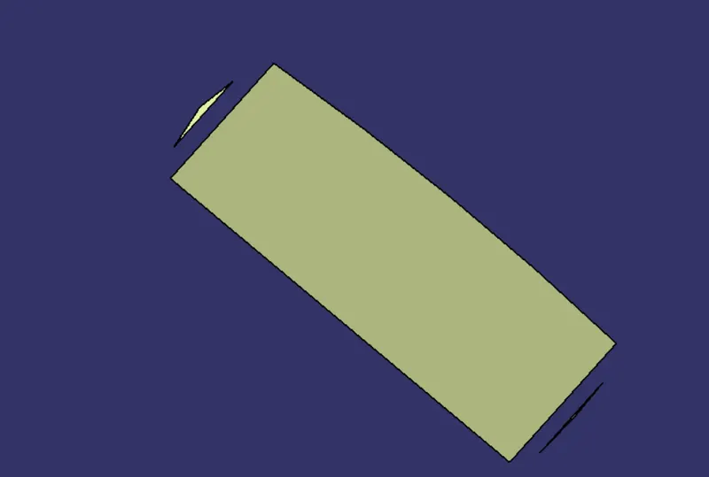
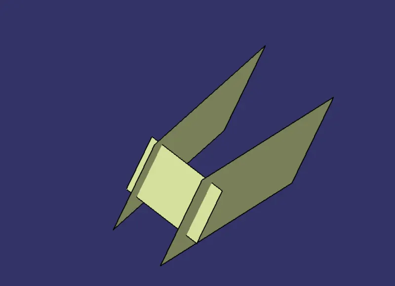
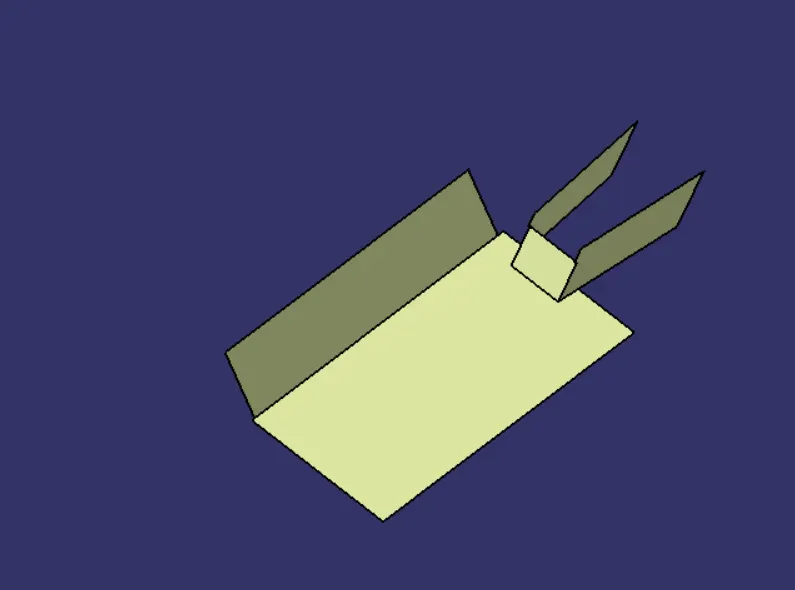
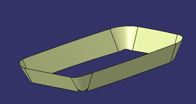
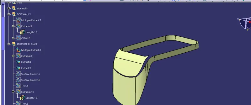
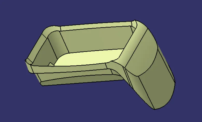
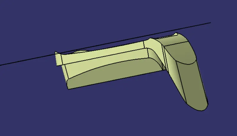
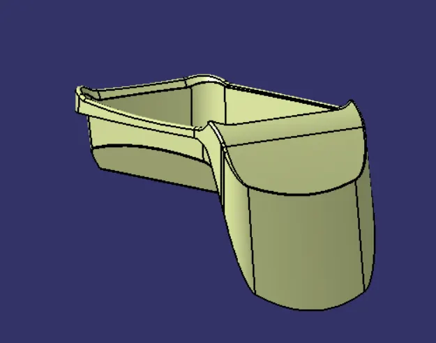
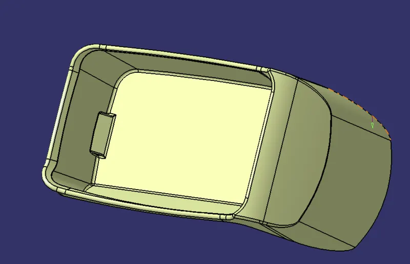
After checking the connectivity we will get into a surface workbench to create a solid part having 2.5mm thickness from the given A surface, i.e the B and C surfaces had to be constructed. The B surface was constructed by extracting all the flat faces on the A surface. Once all the faces were extracted, untrimmed, extrapolated, and trimmed to give a surface similar to that of the A surface. The surface was then offset by 2.5 mm in the direction where the B surface was needed.
CLASS-C :
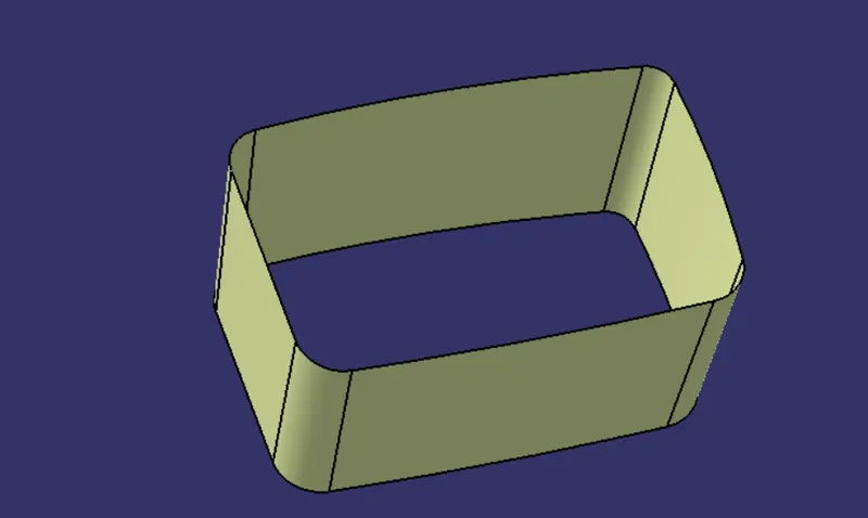
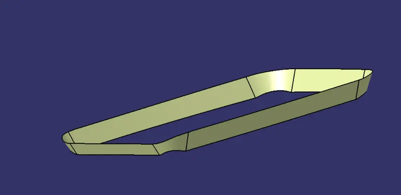
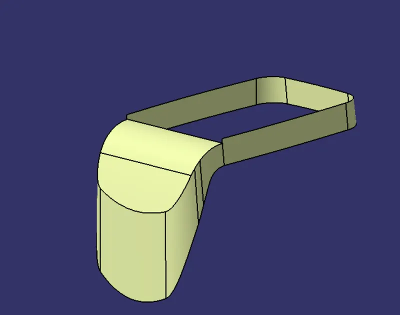
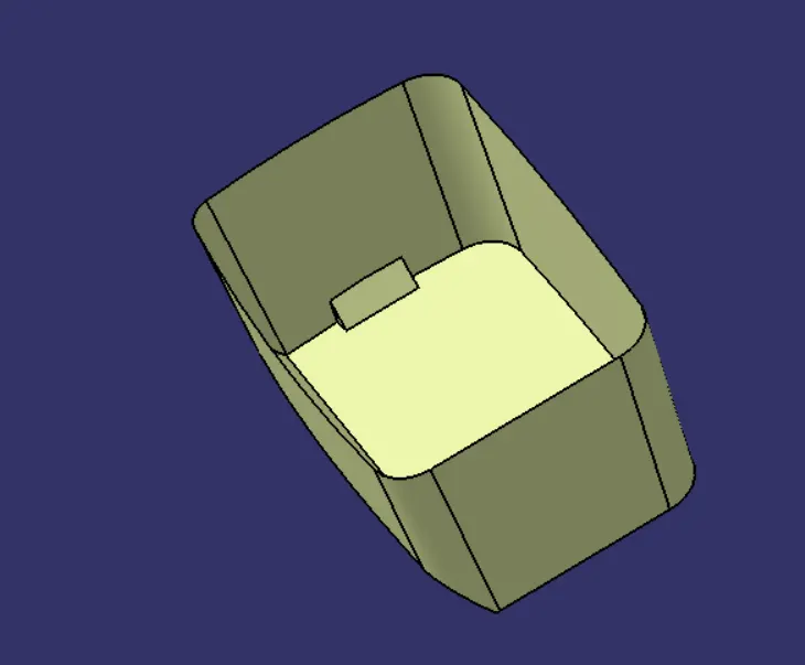
To construct the C surface, a boundary was created using the Boundary tool and the A surface was used as a reference. A surface was created using the Sweep tool-draft option, the tooling axis was selected as the draft direction and a draft angle of 3 degrees was given. The A surface was extrapolated by 2 mm using point propagation and all three surfaces were trimmed to obtain the final part body.
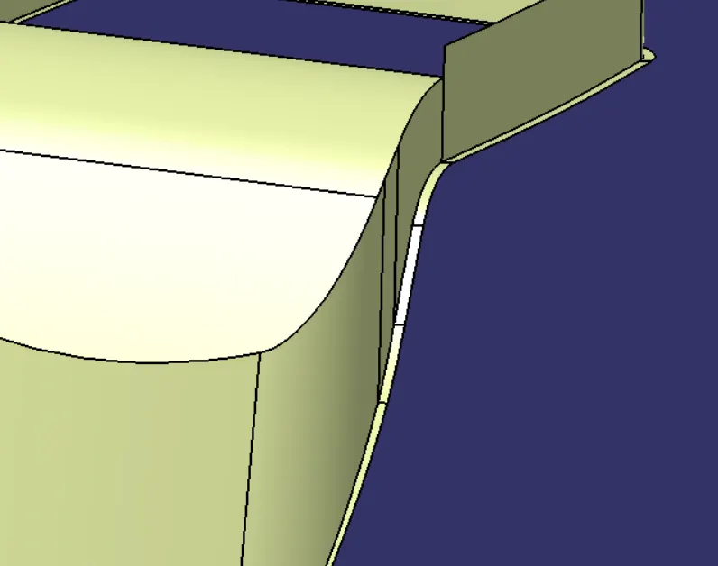
here I have used the Close Surface feature to make a solid body from the surface.
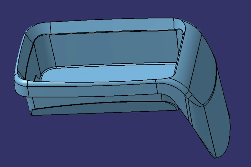
Performing draft analysis on the final plastic component:
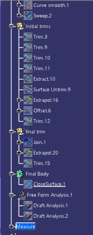
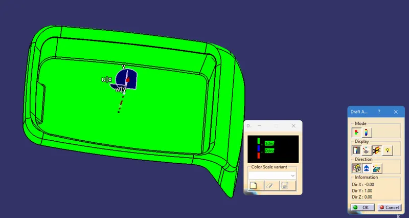
Now, draft analysis was carried out on the final body by inserting a Feature draft analysis. The part body needed to be in customized view with material mode on. The first step was to turn on the compass option and drag the compass and place it in the tooling direction in the correct orientation. Once it was placed, it has to be locked in that position. Then an 'x' cursor appears as we hover over the body and by clicking on it, the draft analysis is shown. The color code was red-negative, blue 0-3 degrees, and green above 3 degrees. Three degrees were chosen since it is the ideal draft angle for plastic components. The body was green which meant that it was a good design and that it would not cause any problems when the part is being extracted from the mold.
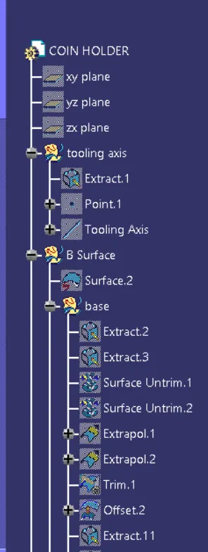
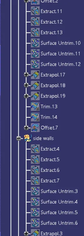
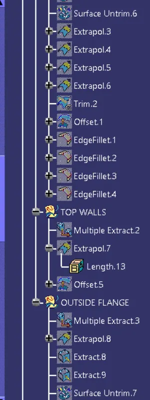
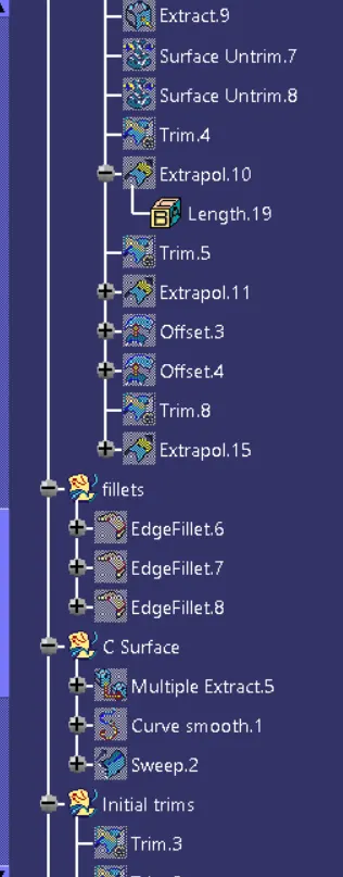
Tree Structure: