Week 8 - Challenge 3 - Coin Holder Design
1. Tooling Axis
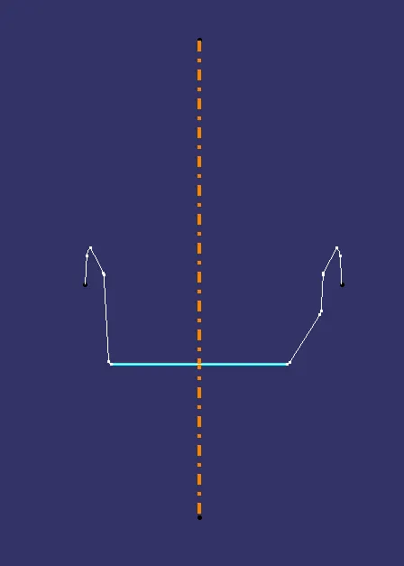
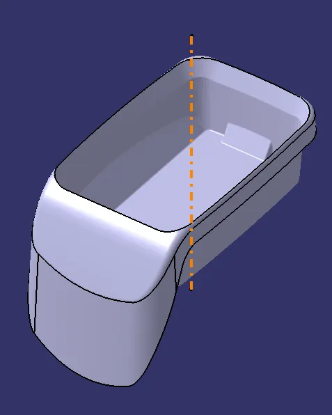
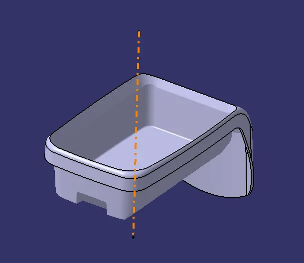
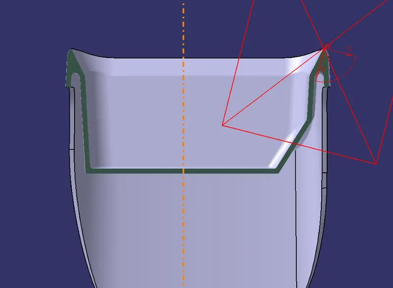
To create the tooling axis the intersection of component is generated with the respective planes (x and y). Since the walls of the coin holder are at 90 degrees or perpendicular to each other the tooling axis is simply created by drawing a line normal to the base.
2. Draft Analysis
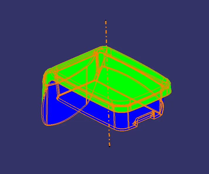
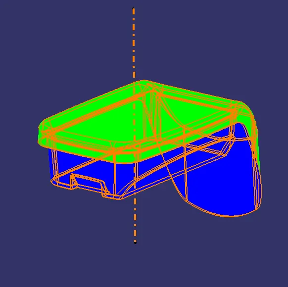
The Draft Analysis command enables you to detect if the part you drafted will be easily removed. This type of analysis is performed based on color ranges identifying zones on the analyzed element where the deviation from the draft direction at any point, corresponds to specified values.
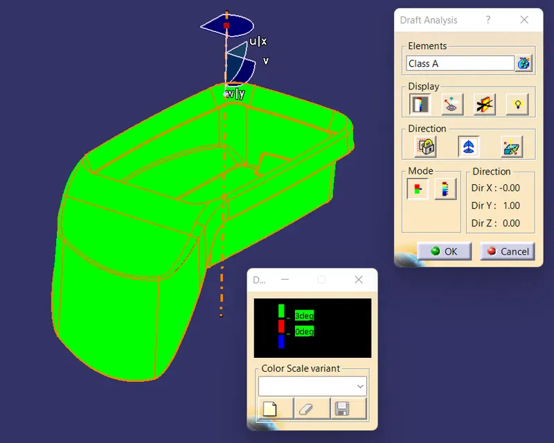
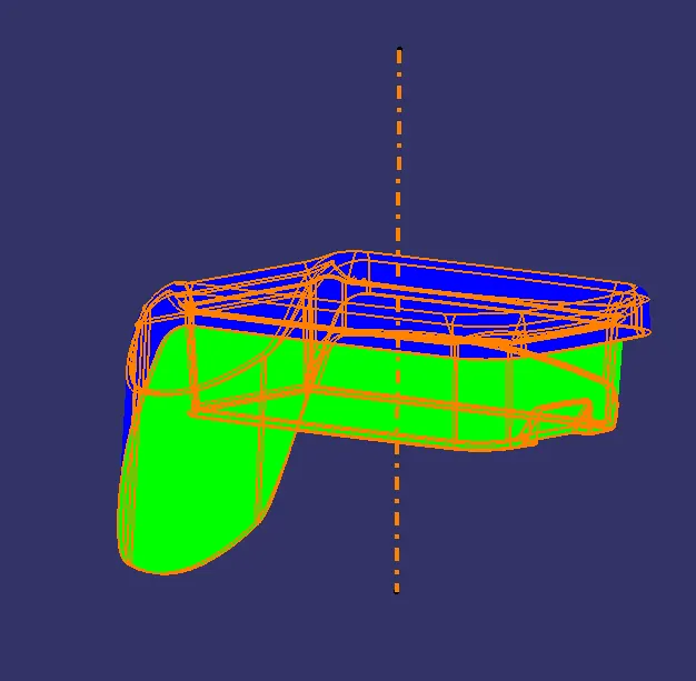
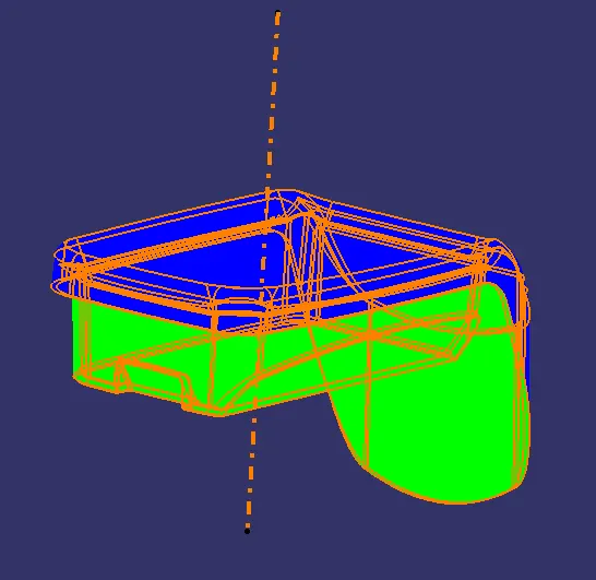
For the color ranges there are 3 colors presented in a simpler legend called the quick analysis mode. Beginning with Green, Red and Blue colors corresponds to the draft angle range of above 3 degrees, 0 to 3 degrees and below 0 degrees respectively.
The ideal value of the draft angle is set at 3 degrees and accordingly the component should be representing the green colour all over the surface which indicates the appropriate value.
i. Class A Surface DA
2. Solid Component DA
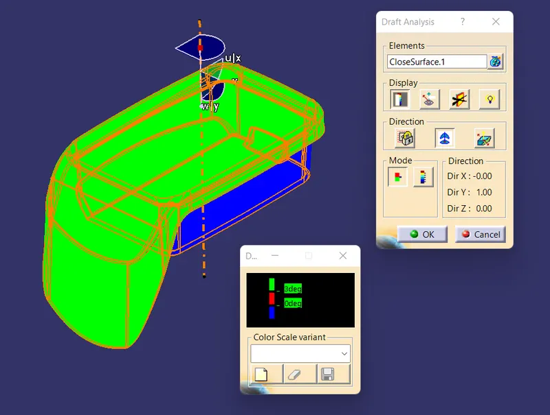
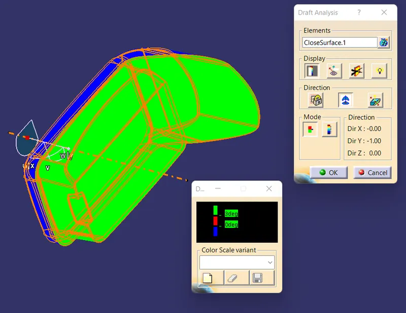
The Parting line is set below the Class A surface which is advisable.
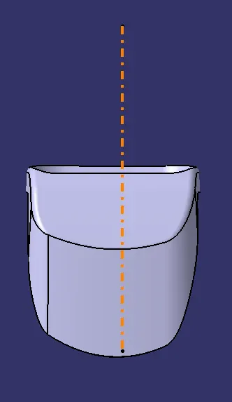
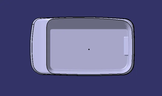
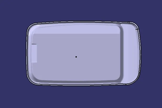
3. Coin Holder Solid
END.