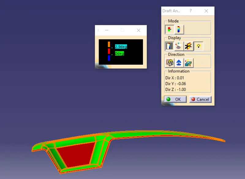
Week 8 - Challenge 2 - Switch Bezel Design
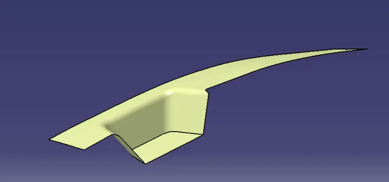
- Screenshots of the Draft analysis report for the given Class-A surface
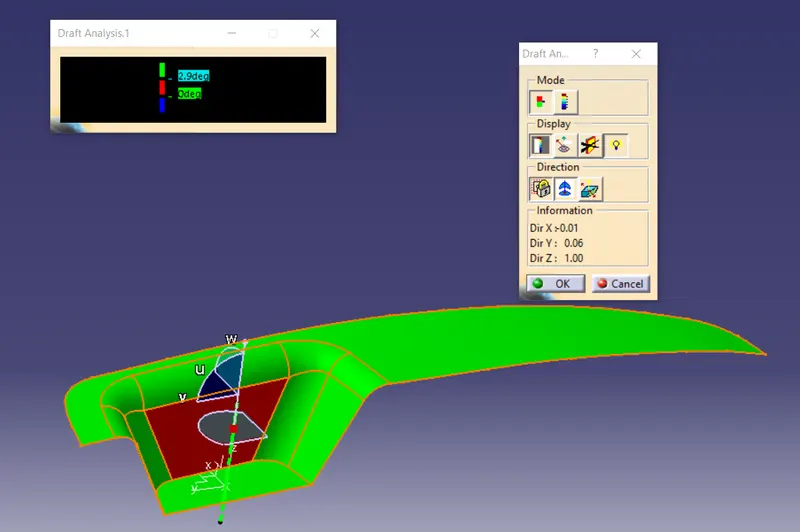
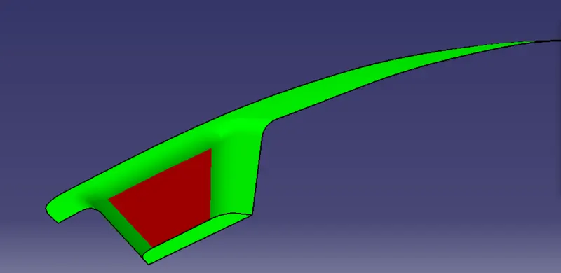
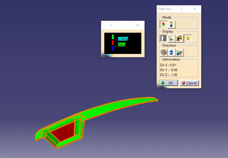
Above is the screenshot of the Class A surface draft analysis.The green color shows the draft angle of 2.9 and more, the red color show the draft andle between 0 and 2.9
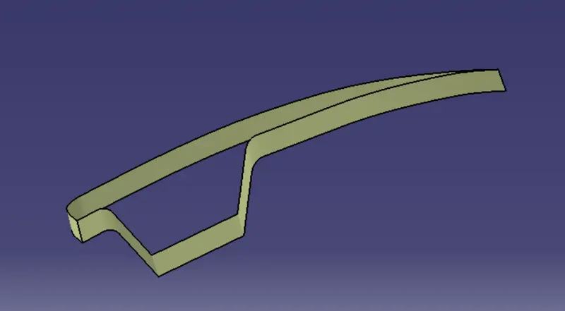
- Screenshots of the Draft analysis report for the final plastic component
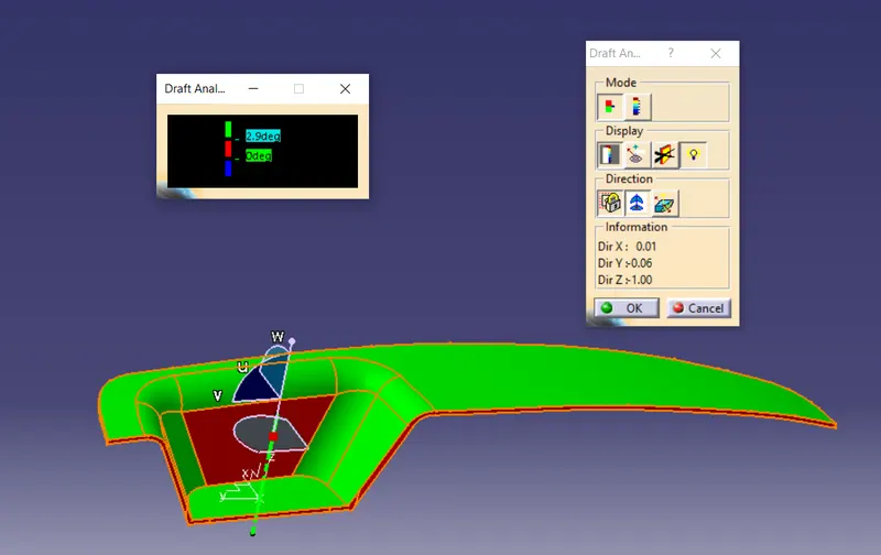
Above is the screenshot of the final plastic surface draft analysis.The green color shows the draft angle of 2.9 and more, the red color show the draft andle between 0 and 2.9
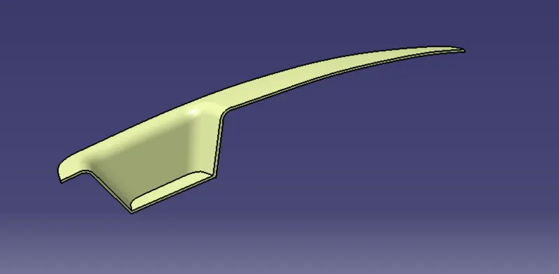
- Screenshots of the solid model with the proper color code of the draft angle in various orientations (Isometric, Front, Side, and Top View)
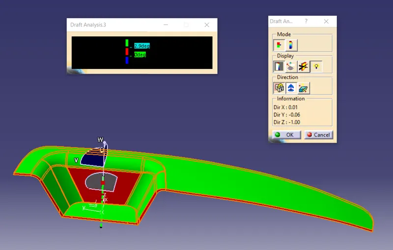
Above is the screenshot of the final solid surface draft analysis.The green color shows the draft angle of 2.9 and more, the red color show the draft andle between 0 and 2.9
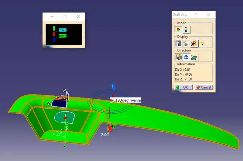
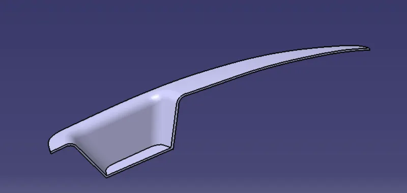
Above is the screenshot of the final solid surface draft analysis.The green color shows the draft angle of 2 and more, the red color show the draft andle between 0 and 2
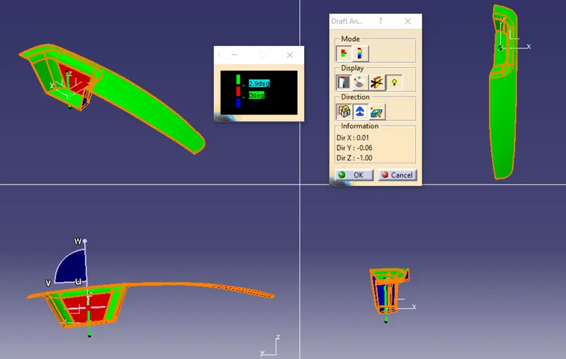
Above it the Isometric, Front, Side, and Top View
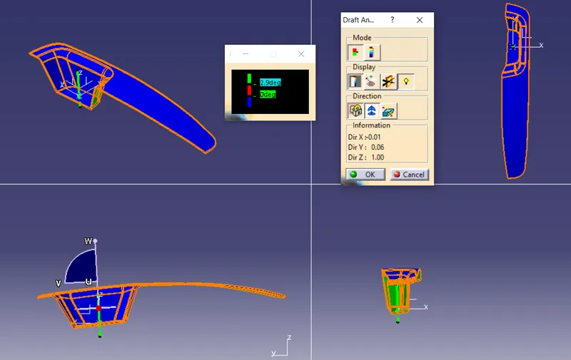
The above figure shows the draft analysis in reverse direction.
DRAFT ANGLE - A draft angle is a taper applied to the vertical walls of the injection-molded component to assist with releasing the part from the mold.Draft angles are a required feature of injection-molded custom parts. A functional part for injection molding has to have draft angles that face both the cavity and core sides. This will reduce the risk of damage to the parts and ensure that they can be ejected from the machine.As the molten plastic flows into the closed die and fills the cavity, the material shrinks inside the mold upon cooling and as a result grips the core.
Tooling axis
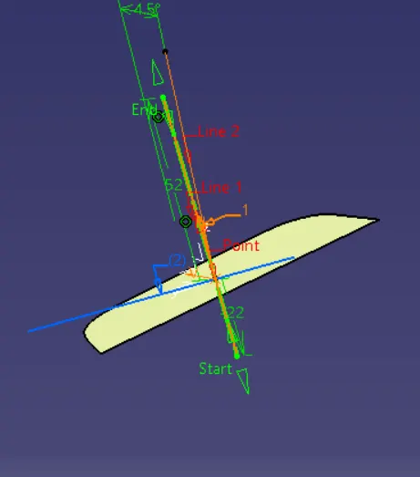
First creating a point on the base and inseting axix system and creating the lines along with the surface as shown in figure
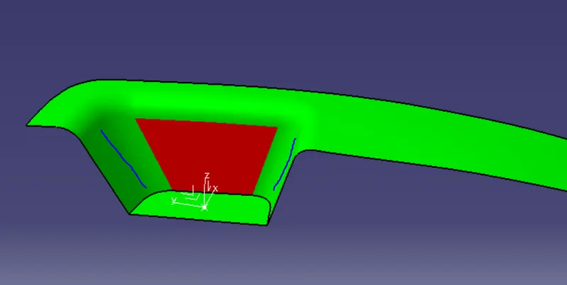
After creating lines along the surface then drawing bisecting line which is the tooling axis for the y direction.
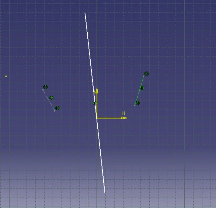
Now again taking point and again inserting axis syaten and makinga line intersecting with the surface and amkinga nother line at 4.5 degree
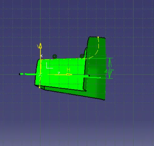
Now draing the besecting line with the previous tooling axis and this line which is at 4.5 degree fron the line which is intersecting with surface

Class A
Class B
Class C
Final plastic solid
Solid Figure
DRAFT ANALYSIS OF SOLID
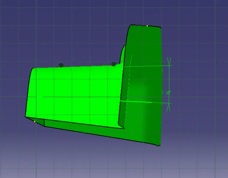
When 4 dgree angle was given
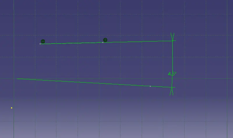
When 4.5 degree was given