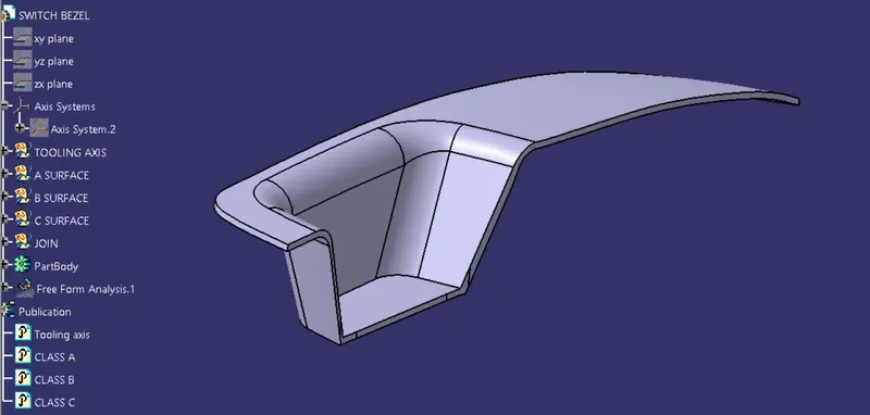
Week 8 - Challenge 2 - Switch Bezel Design
Tooling axis creation:
- First analysis of class A surface should be made to decide the best direction, or the direction of the lowest manufacturing cost which happens to be on the Z axis, where the blue surfaces highlighted is what concerns the manufacturer
- Next blue side surfaces were intersected along the YZ plane of an inserted axis system in the base center, and two tangent lines were drawn for each inclined side, and there tooling axis would be the bisector of the two
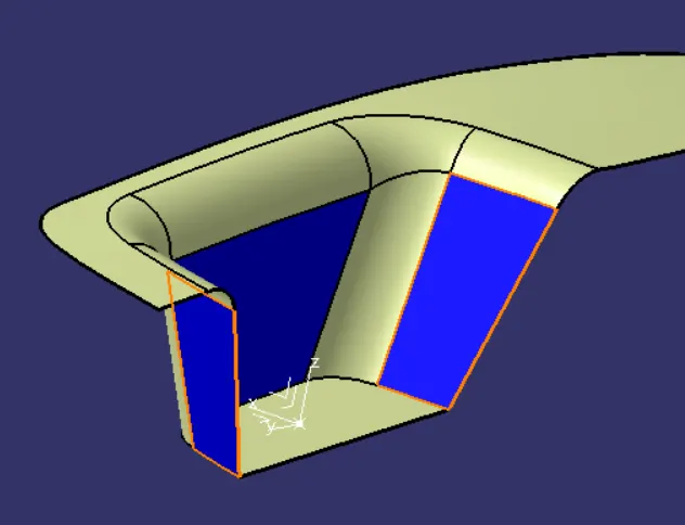
- Next the mid blue surface was intersected on the XZ axis of the same axial system, and a tangent line drawn. however no bisecting line was there to decide the tooling axis for this typical surface so theoratically a line passing through the axis system origin was drawn to be 3 deg apart from the first line
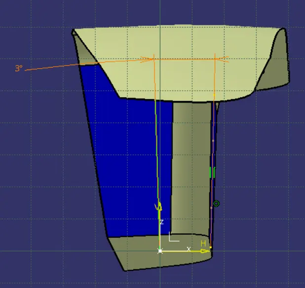
- However after reaching the draft analysis stage, it was obvious that a 3deg between these two lines was not sufficient to clear the part so a procedure of trial and error was followed from values of 3,4,5 until it appears that 6 is the value sufficient to clear this exact face
- Finally the tooling axis is the bisector of the outputs of the two sketches drawn.
Draft analysis:
- After coinciding the compass on the tooling axis and lock it, the inclined mid side was not cleared as stated earlier , and after ajustments made it was cleared using a draft angle of 3, however the sides were not
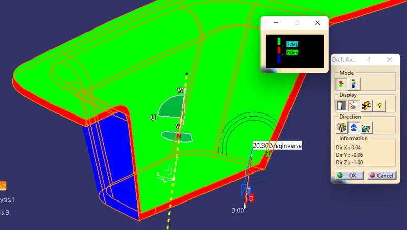
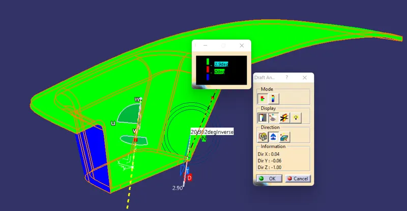
- This is obviously a result of using a smooth curve for sweeping class A along the tooling axis, so after reducing the draft value to 2.9 the part was fully cleared and the draft analysis result is satisfactory
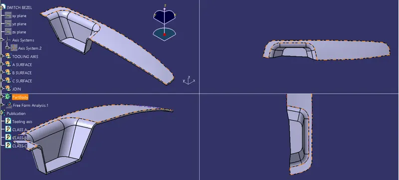
Tree structure, publication and final solid output screenshots: