Week 8 - Challenge 2 - Switch Bezel Design
Aim : To publish the Tooling Axis Class A, B, and C surface for Switch Bezel & analysis the draft.
Objective :
Create the Switch Bezel Plastic component through the given Class-A surface. To begin with, the tooling axis for the given Class-A Surface should be created meeting the requirements of the draft angle and at the end perform the Draft analysis on the model.
Note:
Take the Thickness of the component to be 2.5 mm
In this challege we analysis the drfat value is correct or not for Switch Bezel we used the part file which given into the challenges
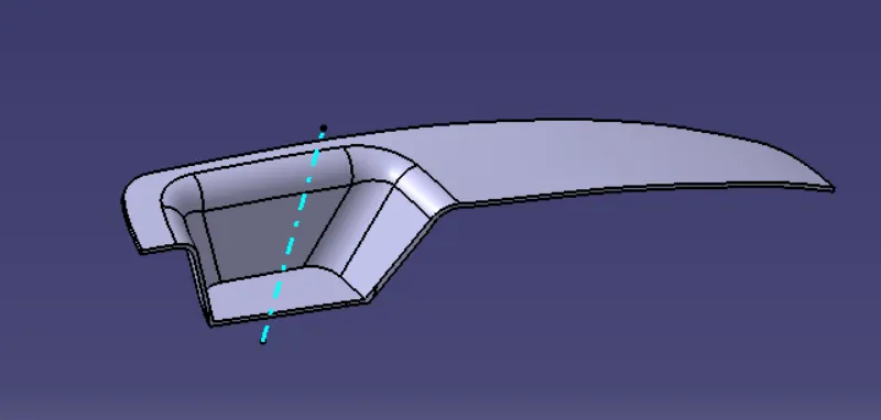
The below image shows that the Class – A surface for given catia part files
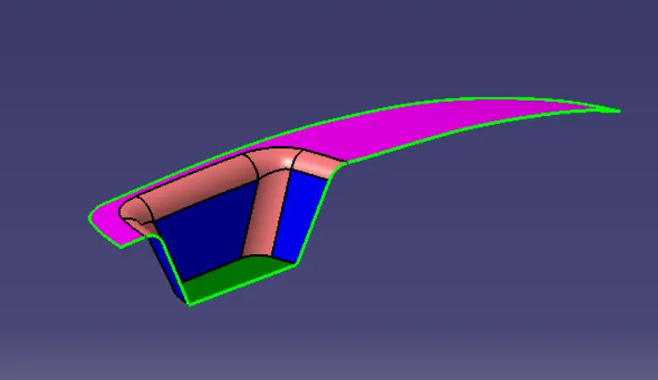
here we 1st step is create tooling axis wihch show cleaerly all part of components and theire draft easily analysis not hidden the any components of ojects
Procedure of creations of Tooling Axis
for tooling axis creation we 1st select point so we create a point on surface as shown in below figure before that we extract that surface than we create the point on it
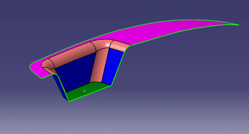
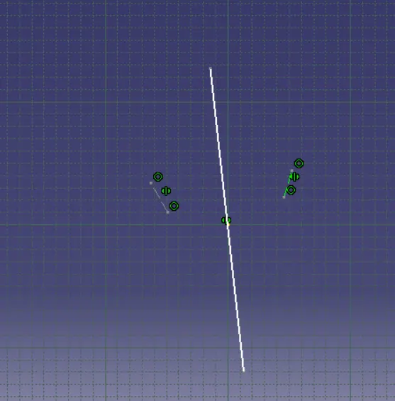
here is we seen in figure 3 surface are bisecting each other so we create two schech one is two surface than so we create two line each surface than bisecting it as shown in figure
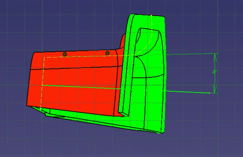
than we create line for 3rd surface so we given the propre tooling axis directions so we create line on 3rd surface by the sketch as shwon in below for 4 degree angle
than we create line by using line command type is bisecting line that time we select reference line 1 is sketch one than second line for second sketch point reference we select point one that we get the tooling axis by z directions than publish it
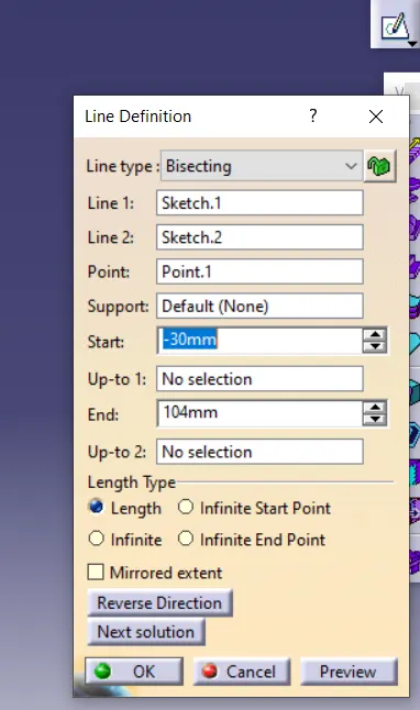
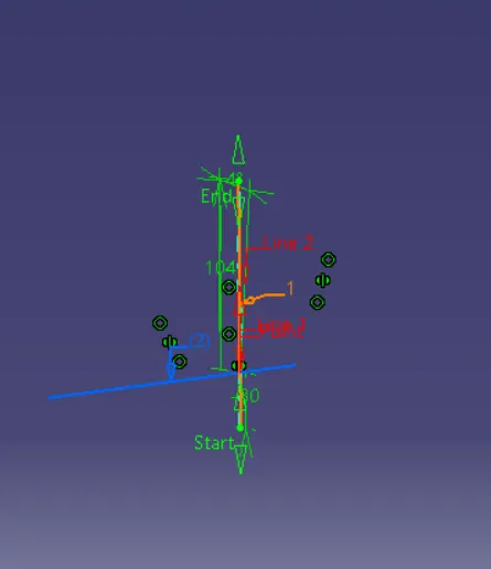
after that we create b surface
Procedure of creations b surface
creation of b surface we required to offset ofthe surface here is clearly mentions it 2.5 mm thickness so we used offset value is 2.5 mm but before of offset we requird extract each surface than surface untrim we get there original surface this method done all required surface for creation of surfaces here is we required the thus surface 1.bezel rest surface 2.walls where 3 walls so we extract 3 times each surface than untrim it. 3.base this all thinks than offset it for 2.5mm than trim get b surface than fillet apply for required edges.
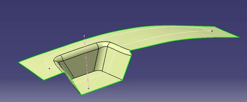
than used c surfaces creations
Procedure of creations c surface
here is we multiple extract the edge than we create soomth curve avoid patch on curve than we used sweep command here is two multiple extract so we use two sweep command Then by using extrapolate command the edges were intersected between the surface corners which eases the trimming operation.Now the required portion of the C surface were trimmed out. below figure is c surface
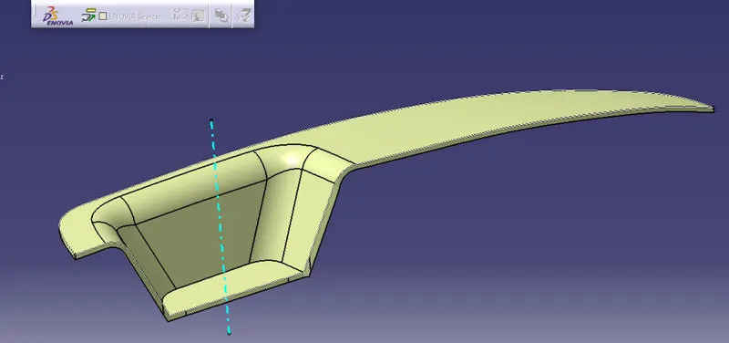
than colosed surface used
PROCEDURE FOR DRAFT ANALYSIS
First the class – A surface is checked before creating the Class –B&C surface and finally the solid body must be analysed. Both can be done by following the below procedures.
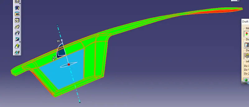
By changing the view mode to custom view parameters – Material mode then the feature draft analysis is enabled.
Then the compass was activated and placed with the tooling axis by dragging the red pointer and then locked it.
Then, by selecting the quick analysis mode, the nominal value will be 3 degrees and checked for the component's draft angle.
The green colour area shows that it satisfies the 3-degree draft angle. If not satisfied then by using the Running point tool the area is measured and then altered to get a successful draft for the created tooling direction.
Note : this challenge we attched the zip files where is placed this challenge catia files.